- Semiconductor BusinessHOME
- Products and Services of Macnica,Inc.
-
technical information

-
Events and Seminars
- Handling Manufacturer
- Support
- Inquiry
- Click here to purchase products
- Semiconductor business e-mail magazine registration
![]()
![]() Narrow down by specifying conditions
Narrow down by specifying conditions
現在2168件がヒットしています。check

Introducing the latest solutions for switching regulators that reduce ripple.
Switching regulator ripple voltage equation
When digital circuits handle high-speed signals, the required jitter specifications become stricter. Therefore, it is necessary to reduce the ripple voltage that affects jitter characteristics. This time, we will consider what should be done to keep the ripples of switching regulators, which affect their jitter characteristics, to a minimum.
V Ripple: Ripple voltage
ΔI L: Inductor ripple current
ESR: ESR of output capacitor
f SW: switching frequency
C OUT: Capacity of output capacitor
The ripple voltage of a switching regulator can be expressed as Equation 1.
From this equation, we can see that as the inductor ripple current (ΔIL) increases, the ripple increases.
Inductor ripple current is defined as 40% of the current required by the load.
Therefore, as the current value required by digital circuits such as FPGAs increases, the ripple increases.
In the current situation where the trend towards lower voltages and higher currents is accelerating, it is not possible to reduce the ripple current in the inductor, so it is necessary to reduce the ripple voltage using other items in Equation 1.
How to reduce ripple voltage in switching regulators
There are three items other than the inductor ripple current in Equation 1:
- Output capacitor equivalent series resistance (ESR)
- Output capacitor capacity (Cout)
- Switching frequency (fsw)
By adjusting these three items, you can reduce the ripple voltage.
1.The ESR of the output capacitor increases in proportion to the ESR, as seen from "Ripple current x ESR" in Equation 1, so it can be reduced by using a ceramic capacitor with a low ESR.
2.The output capacitor's capacity is included in the denominator of Equation 1, so you can understand that increasing the output capacitor's capacity will reduce the ripple. Capacity can be increased by installing more ceramic capacitors. However, the board area becomes larger and the cost increases, so I would like to keep the number of devices installed to a minimum.
3.The switching frequency is also included in the denominator of Equation 1, so increasing the switching frequency will reduce the ripple. However, generally speaking, increasing the switching frequency increases switching loss and reduces efficiency. Therefore, it is necessary to consider increasing the frequency while making sure that there is no problem with efficiency.

Figure 1 shows the ripple voltage and inductor current waveforms for the LTC3616 synchronous DC/DC converter. The ripple is very small, only a few mV.
Switching frequency and efficiency
Increasing the switching frequency increases switching losses and reduces efficiency.
Until a few years ago, 2MHz was the highest switching frequency. The latest devices are 4~5MHz products.
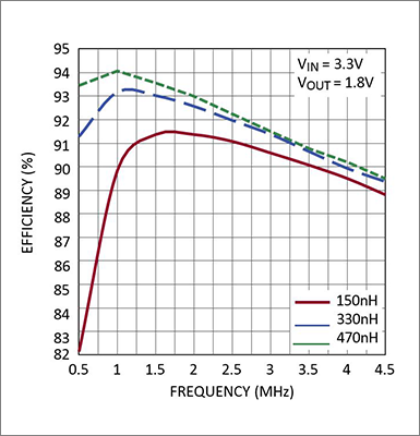
Figure 2 shows the switching frequency vs. efficiency curve for the LTC3616 synchronous DC/DC converter.
The efficiency peaks when the switching frequency is 1 to 2MHz, and the efficiency gradually decreases up to 4MHz.
However, efficiency is not a problem as it achieves approximately 90% even at 4MHz.
Below is a list of monolithic synchronous step-down regulators with adjustable switching frequencies up to 4MHz.
By using this product, you can design circuits while minimizing ripple and suppressing jitter components in digital circuits.
| model number | operating frequency | feature | Input voltage range |
| LTC3310 | 5MHz | 10A, Monolithic Synchronous Step-Down Regulator, Silent Switcher 2 | 2.25V~5.5V |
| LTC3309B | 3MHz~10MHz | 6A, Monolithic Synchronous Step-Down Regulator, Silent Switcher 2 | 2.25V~5.5V |
| MAX17626 | 2MHz or 4MHz | 700mA, Monolithic Synchronous Step-Down Regulator in Small Package | 2.7V ~ 5.5V |
| MAX17624 | 2MHz or 4MHz | 1A, Monolithic Synchronous Step-Down Regulator in Small Package | 2.7V ~ 5.5V |
| LTC3315B | 6MHz | Dual 2A, monolithic synchronous buck regulator | 2.25V~5.5V |
| LTC3636 | 500MHz~4MHz | Dual 6A, Single 12A Monolithic Synchronous Step-Down Regulator | 3.1V~20V |
| LTC3623 | 400kHz ~4MHz | ±5A, Monolithic Synchronous Step-Down Regulator Programmable with a Single Resistor | 4~15V |
| LTC7124 | 500kHz~4MHz | Dual 3.5A, Single 7A Monolithic Synchronous Step-Down Regulator | 3.1V~17V |
| MAX17620 | 4MHz | 600mA, Monolithic Synchronous Step-Down Regulator | 2.7V~5.5V |
| LT3616 | 4MHz | 6A, Monolithic Synchronous Step-Down Regulator | 2.25~5.5V |
important point! Even if you use a good product, the ripple is large!
By using a product with a switching frequency of 4MHz, it is possible to obtain a small and clean voltage like the ripple voltage in Figure 1. However, as described in the second half of the switching regulator design method, if you make a mistake in the board pattern design (artwork), you will not be able to obtain the desired ripple waveform.
Once a large switching noise is added to the ripple due to the board pattern design, it is often not possible to remove it by adding a capacitor, so be careful. Be sure to refer to the manufacturer's recommended pattern when designing.
If you would like to learn the basics of pattern design for switching power supplies, we recommend that you take the Analog Solutions Power Supply Design Seminar <Free>.
To minimize layout impact
Noise due to the inductance component of the wiring pattern due to the wiring on the board and the inductance component due to the IC leads and bonding wires affects the ripple voltage.
Analog Devices' µModule® is a solution that minimizes this inductance component.
The product lineup that supports a switching frequency of 4MHz is as follows. Recommended for those who do not want to spend time on layout design or those who want to build a system with as little ripple as possible.
| model number | feature | Input voltage range |
| LTM4658 | 10A, Step-Down DC/DC μModule Regulator | 2.25V~5.5V |
| LTM4670 | Quad 10A, Dual 20A, Single 40A, Low VIN Quad µModule Regulator | 2.25V~5.5V |
| MAXM17624 | 1A, Himalaya uSLIC Step Down Power Module | 2.9V~5.5V |
| MAXM17626 | 600mA, Himalaya uSLIC Step Down Power Module | 2.7V~5.5V |
| LTM4655 | Dual 4A, single 8A step-down, or 50W inverting µModule regulator | 3.1~40V |
| LTM4625 | 5A Step-Down DC/DC μModule Regulator | 4~20V |