- Semiconductor BusinessHOME
- Products and Services of Macnica,Inc.
-
technical information

-
Events and Seminars
- Handling Manufacturer
- Support
- Inquiry
- Click here to purchase products
- Semiconductor business e-mail magazine registration
![]()
![]() Narrow down by specifying conditions
Narrow down by specifying conditions
現在2183件がヒットしています。check

Control method for efficient use of energy
In recent years, regulations on standby power have become stricter, especially in the EU. In addition, it is necessary to control power supply ON/OFF in small devices that operate on batteries, such as mobile devices and sensor terminals, in order to use energy efficiently.
Such cases can be easily realized by using the LTC2955.
Pushbutton On/Off Controller LTC2955 with Auto Power On
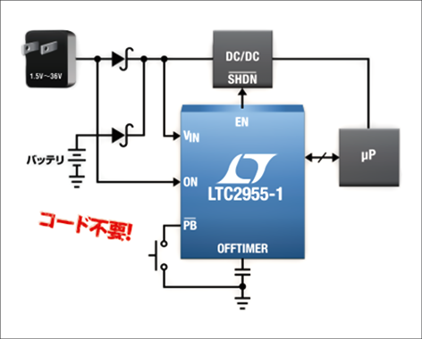
The LTC2955 is a pushbutton ON/OFF controller that manages and controls power supplies from 1.5V to 36V depending on the pushbutton and power connection status.
The LTC2955 does more than just a standard pushbutton control that powers up at the push of a button.
It can also be controlled to automatically power up the system when power is supplied from the main or auxiliary power supply, and power down the system when a push button is pressed.
In addition, it is possible to protect the battery by shutting down the software with a timer by monitoring the no-operation state, and by monitoring the drop in the power supply voltage and automatically powering down the consumption current to 1.2μA.
It works standalone, so no software writing is required.
The LTC2955 makes it easy to add a power on/off function commonly used in mobile handsets.
The wide operating range of 1.5V to 36V makes the LTC2955 useful in a wide variety of battery applications, from portable devices and sensor terminals to automotive electronics.
A block diagram of the LTC2955 is shown on the left.
LTC2955 OPERATION AND KEY FEATURES
Auto on/off combinations can be selected with the mode select pin.
With a power good output, an interrupt output and a kill input, the LTC2955 is easy to interface with microprocessors, even for microprocessors that cannot use interrupts, a pushbutton off timer can be set. increase.
Key features of the LTC2955:
・Automatic turn-on using voltage monitor input
・Wide input power supply range: 1.5V to 36V
・Low current consumption: 1.2μA
・Push button (/PB) input with reduced bounce
・/PB input ESD resistance (human body model): ±25 kV
・Enables DC/DC converter control with low leakage EN output (LTC2955-1)
・High voltage/EN output to drive P-channel MOSFET (LTC2955-2)
・Microprocessor can be controlled with a simple interface
・Adjustable off timer
10-pin 3mm x 2mm DFN and 8-pin ThinSOT(TM) packages
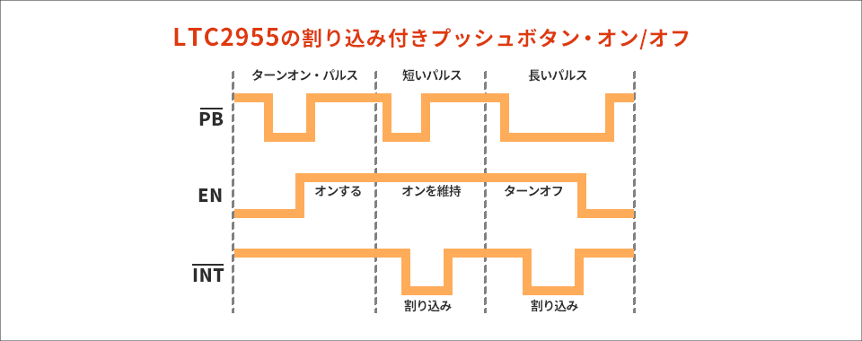
The operation image diagram of LTC2955 is shown below.
Introduction of LTC2955 Related Products
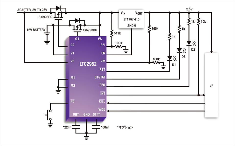
In addition to the LTC2955, there is also the LTC2952, which has an ideal diode PowerPath function for low loss automatic switching when there are two input sources, and for more sophisticated control.
A block diagram of the LTC2952 is shown below.
Inquiry
If you have any questions regarding technical consultations or inquiries regarding the articles posted, or general questions about Analog Devices products, please contact us here.