![]()
![]() Narrow down by specifying conditions
Narrow down by specifying conditions
現在1888件がヒットしています。check

Beware of overvoltage and power sequence!
オペアンプの電源は、入力信号が印加されるのと同時か、その前に確立されていなければなりません。さもなければ、過電圧やラッチアップによる問題が生じてしまうおそれがあるからです。 (出典:アナログ・デバイセズ社「オペアンプに対する不適切な電源シーケンス、そのリスクを分析する」)
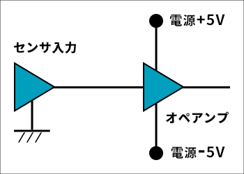
Consider using an op amp as the input circuit for an external sensor (Figure 1).
The correct procedure is to have the op amp powered up before the sensor signal is applied to the op amp. But is there any guarantee that this procedure will always be followed correctly?
Op amps can be easily protected from unexpected input signals by using channel protector products.
Product Description of 4-Channel Protector (ADG5462F)
The ADG5462F is a 4-channel protector that provides ±55V overvoltage protection.
Simple to use, they are inserted in series in the signal path to protect sensitive components from overvoltage.
No sequence is required, and when the power is not turned on, the input line is cut off to strongly protect the delicate input circuit. Low on-resistance (10Ω Ron) after power-on does not affect the input line.
You can set the upper and lower limits to cut overvoltage not only before the power is turned on, but also after the power is turned on. The set voltage can be set by directly connecting the op amp power supply or by resistive voltage division.
Latch-up immunity by high-voltage process. Even if the number of elements increases, the worry does not increase.
Main features
• Input pins are protected against voltages between −55 V and +55 V when power is off.
• Trench isolation protects against latch-up.
• Optimized for low on-resistance and on-resistance flatness.
・The operation status of the channel is digitally output by overvoltage detection.
・The ADG5462F operates with a ±5 V to ±22 V dual power supply or an 8 V to 44 V single power supply.
Terminal function
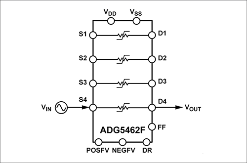
Sx: Input (source) terminal
Dx: Output (drain) terminal
VDD: Power supply (+)
VSS: Power supply (-)
POSFV: Fault detection voltage level (+)
NEGFV: Fault detection voltage level (-)
DR: Failure output setting input (Hi-Z / failure detection level)
FF: Fault status output
GND: reference potential
Protection circuit example
Here are three examples of protection circuits using the ADG5462F.
Usage 1: Cut off the input from the sensor before turning on the power
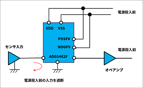
When using an optical system element as a sensor, there are times when the output of the sensor is input to the operational amplifier before the operational amplifier is turned on.
In such cases, the problem can be avoided by using the ADG5462F as shown in Figure 3 to isolate the sensor and operational amplifier.
The ADG5462F has a withstand voltage of ±55 V even without power, so even if there is a sensor signal input to the ADG5462F before power is turned on, it will not fail.
Usage 2: Cut off excessive input
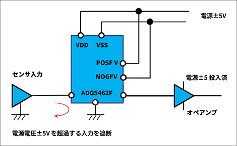
The range of signals that can be input to the operational amplifier is within the range of the power supply applied to the operational amplifier, so in the case of Figure 4, it is within ±5V.
Even if the operational amplifier is calculated and designed so that an overvoltage of ±5V or more is not applied, the sensor monitors information from the natural world, so it may suddenly output a signal with a level higher than expected.
The connection example in Fig. 4 is a solution for such cases.
In the case of Figure 4, when the input signal exceeds the ±5V threshold voltage set by the POSFV and NOGFV pins, the protector detects overvoltage and shuts down the output to protect the operational amplifier.
Usage 3: Adjust the cut-off conditions according to the subsequent circuit
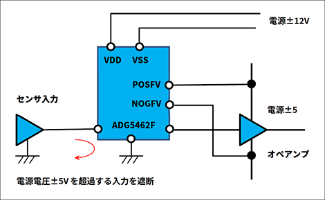
This is an application of Usage 2.
Even if the power supply voltages of the preceding and subsequent circuits are different, the protector detects overvoltage and shuts down the output to protect the operational amplifier when it exceeds the threshold voltage of ±5V set by the POSFV and NOGFV pins.
Inquiry
If you have any questions about Analog Devices products, please contact us here.
Click here for recommended articles/materials
・ Plus/minus power supply design
・ High-precision operational amplifier ADHV4702-1 that can directly input 220V