- Semiconductor BusinessHOME
- Products and Services of Macnica,Inc.
-
technical information

-
Events and Seminars
- Handling Manufacturer
- Support
- Inquiry
- Click here to purchase products
- Semiconductor business e-mail magazine registration
![]()
![]() Narrow down by specifying conditions
Narrow down by specifying conditions
現在2168件がヒットしています。check

What are the advantages of electronic breakers?
If the power supply is short-circuited due to circuit failure or operational error, overcurrent will flow, which not only leads to secondary failure of the power supply, but also causes fires and other accidents due to heat generation of circuit components. For this reason, many power supplies have protection functions such as current limiting, but I think many also include a fuse to improve reliability.
However, the fuse has a large error in the fusing current, and if a margin is not provided, it may be blown by the rush current when the power is turned on. Also, once it is fused, it needs to be replaced, so there is a drawback that maintenance is troublesome.
By using an electronic circuit breaker, the protection current can be set to a precise value, and it can be maintenance-free because it recovers when the power is turned on again.
Current sense amplifier LT6118 for use in a wide range of power systems
The LT6118 is a high side current sense amplifier with power-on reset, internal reference and comparator, specified for operation from –40°C to 125°C, making it suitable for industrial and automotive applications. increase.
It can also operate from 2.7V and has a maximum rating of 60V, allowing it to be used in a wide range of power systems.
Below are the features and functional block diagram of the LT6118.
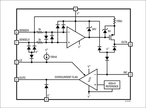
Features of the LT6118
- Fast step response: 500ns
- Internal 400mV Precision Reference
- Built-in comparator
- Power-on reset function
- Fast response time: 500ns
- Total Threshold Error: ±1.25% Max
- Wide supply voltage range: 2.7V to 60V
- Specified over a temperature range of -40°C to 125°C
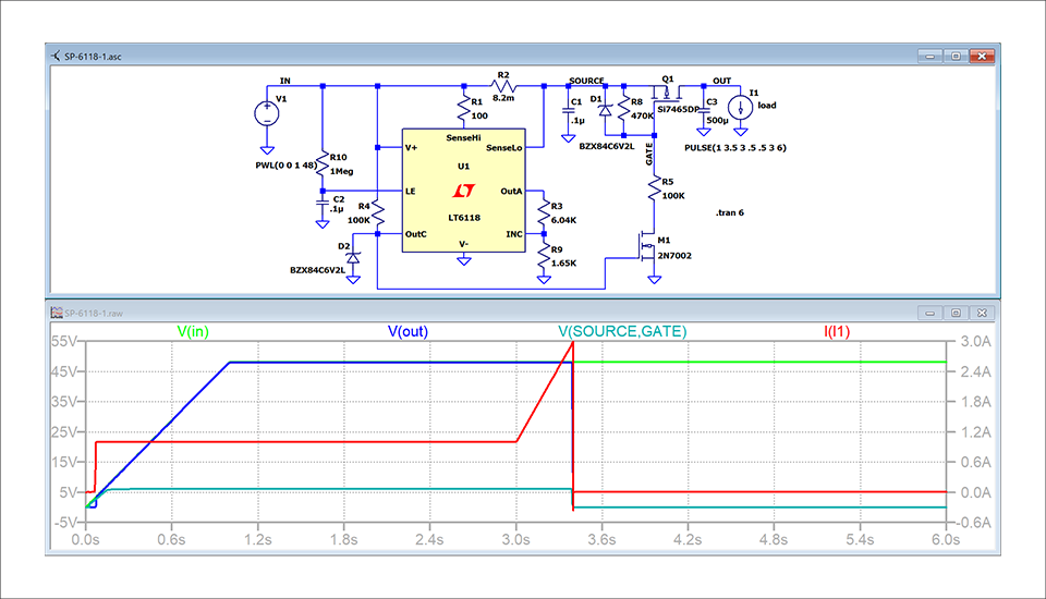
Example circuit and results using LTspice
Below is an example circuit with LT6118 using LTspice, P-MOSFET (Q1) cuts off the circuit when about 3A is exceeded at 48V supply.
The 500uF capacitor on the output is to ensure that the output will not be cut off by the power-on rush current, and does not actually need to be used in the circuit.
The current flowing through the output load is detected by the shunt resistor R2 and output to OutA. This current is developed through resistors R3, R9 and applied to the comparator input INC, which is compared to an internal 400mV reference to detect overcurrent.
The Zener diode D2 connected to OoutC is to limit and protect M1's N-MOSFET Vgs, and D1's Zener diode is likewise to limit and protect Q1's Vds.
The time constant of R10 and C2 provides a dead zone during power-on, preventing the breaker from operating due to the rush current that occurs when the bypass capacitor is charged when the power is turned on.
For lower supply systems, say 5V, D1, D2 are not required and R5 and R10 should be adjusted to 1/10th the value.
Click here for recommended articles/materials
To download LTspice, read this article.
LTspice article list: Let's use LTspice!
Inquiry
If you have any questions about Analog Devices products, please contact us here.