![]()
![]() Narrow down by specifying conditions
Narrow down by specifying conditions
現在2003件がヒットしています。check

In the previous article Let's use LTspice - Let's encrypt the SPICE model, we introduced how to encrypt the SPICE model. In this article, I would like to create a variable resistor.
When performing a circuit simulation, there are times when you want to check the movement of node voltages and currents by varying resistance values. However, LTspice does not have component elements such as variable resistors that change the resistance value.
So, this time, I will introduce a method to change the resistance value.
If you are just starting LTspice, we recommend that you look at the "basics" from the list below.
Let's use LTspice series list is here
Also, if you would like to see a video on how to write a basic circuit and how to execute it, there is an on-demand seminar that does not require you to enter personal information, so please take a look if you are interested. Detailed information about the seminar is also provided to those who fill in the questionnaire.
LTspice On-Demand Seminar - Function check with RC circuit -
Let's set the resistance parameters with a voltage source!
Usually in LTspice, the parameter of the resistance element is set to a constant such as R = 10Ω, but it is possible to set it with R = <formula>. Also, by specifying the node voltage in the <expression>, the resistance value can be varied.
I would like to do a simulation. Here, the resistance value is varied from 1k to 10k.
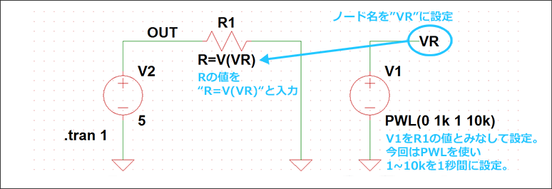
The circuit diagram you entered and the procedure for creating it are as follows.
- Prepare the voltage source V1 to set the node voltage. Here, the node is "VR".
- Consider the voltage value of the voltage source V1 as the resistance value. Here, set the voltage source to PWL (0 1k 1 10k) in order to change the slope from 1k to 10k per second.
- Set the value of resistor R1 to R=<expression>=V(VR).
- Set up the transient analysis and apply a voltage source V2 (here 5V) to the resistor and run the simulation.
By setting V(out)/I(R1) from "Add Trace" on the simulation result waveform viewer as shown in Fig. 2, it is possible to display the simulation result with the resistance varied with respect to the time axis. I can do it.
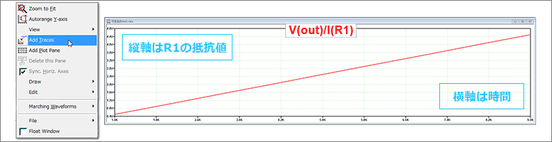
By using this method, you can change the resistance value in transient analysis, so you can check the voltage and current changes when the resistance changes.
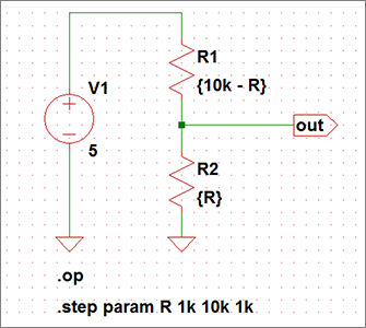
Creating a Variable Resistor Using .OP Analysis
Let's use LTspice - Let's change parameters with ".step"
Here, resistors R1 and R2 are regarded as variable resistors, and a simulation is performed of the divided node voltage when a DC voltage source is connected.
The horizontal axis is the changed resistance value, and the vertical axis is the divided voltage value from the variable resistor.
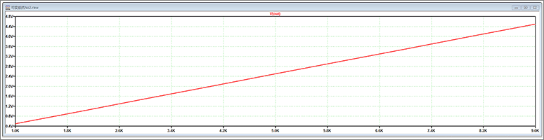
In this way, the .step command and .OP analysis can be used to easily check the change in the voltage node when the resistance value is changed.
LTspice demo file verified this time
Simulation model implemented this time
At the end
This time, I introduced an example of how to create a variable resistor that changes the resistance value.
If you haven't used LTspice yet, please download LTspice from the link below!
Please try once.
Download LTspice here
We also hold regular LTspice seminars for beginners. You can learn the basic operation of LTspice, so please participate.
Click here for LTspice seminar information
Click here for recommended articles/materials
List of articles: Let's use LTspice Series
LTspice FAQ: FAQ list
List of technical articles: technical articles
Manufacturer introduction page: Analog Devices, Inc.
Click here for recommended seminars/workshops
Inquiry
If you have any questions regarding this article, please contact us below.
Analog Devices Manufacturer Information Top
If you want to go back to Analog Devices Manufacturer Information Top, please click below.