- Semiconductor BusinessHOME
- Products and Services of Macnica,Inc.
-
technical information

-
Events and Seminars
- Handling Manufacturer
- Support
- Inquiry
- Click here to purchase products
- Semiconductor business e-mail magazine registration
![]()
![]() Narrow down by specifying conditions
Narrow down by specifying conditions
現在2153件がヒットしています。check

Let's use LTspice in the previous article -In the method of checking the maximum and minimum voltage values with ".meas", introduce the ".masure" command that reads the minimum and maximum values of the output voltage when the load of the power supply IC changes. I was allowed to.
This time, we will introduce a parametric analysis method that uses the ".step" command to step-by-step change the constants in the schematic and perform a simulation.
If you are just starting LTspice, we recommend that you look at the "basics" from the list below.
Let's use LTspice series list is here
Also, if you would like to see a video on how to write a basic circuit and how to execute it, there is an on-demand seminar that does not require you to enter personal information, so please take a look if you are interested. Detailed information about the seminar is also provided to those who fill in the questionnaire.
LTspice On-Demand Seminar - Function check with RC circuit -
Let's simulate the charging time to the capacitor!
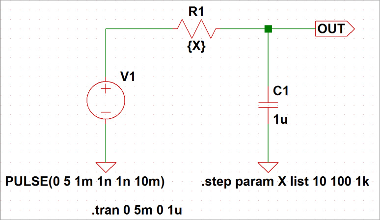
Let's check the waveform on the time axis using the ".step" command for the capacitor charging time when the resistance value is changed to 10Ω, 100Ω, and 1kΩ in the RC circuit.
Using the .step command
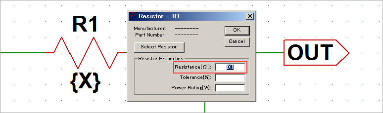
To define the parameters of the resistor component with variables, right-click on the resistor and enter {X} as the Resistance value.
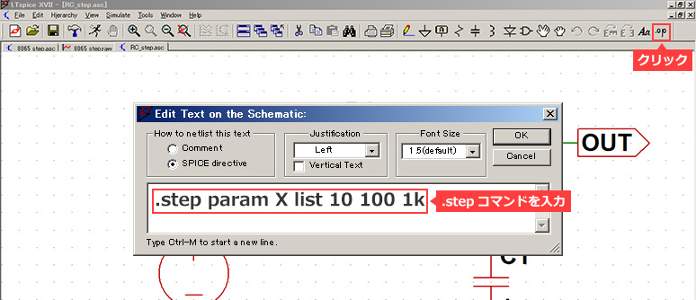
Select [SPICE directive] from Edit on the toolbar. Edit Text on the schematics will open, so add the .step command here.
This command either linearly or logarithmically changes the value of the variable specified by the parameter (here X), or specifies the value of the parameter by a list. This time we set three values as a list. Therefore, the description is ".step param X list 10 100 1k", and it is executed while changing the parameter X to each value in the list.
Run the simulation
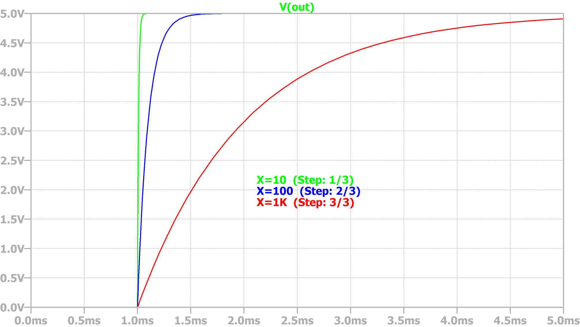
When transient analysis was performed, three types of waveforms were generated, as shown below. When the resistance value was 10 Ω the green waveform was displayed, when it was 100 Ω the blue waveform was displayed, and when it was 1 kΩ the red waveform was displayed. In this way, it is possible to obtain results by changing parameters in a single simulation, making it possible to perform circuit verification efficiently.
Let's apply the ".step" command to the evaluation of power supply ICs!
Let's use LTspice in the previous article -In the method of checking the maximum and minimum voltage values with ".meas", the maximum and minimum voltage values (Peak to Peak) of the output voltage during load fluctuations of the μModule series LTM8065 of the step-down regulator I read.
In addition, use the ".step" command to change the load current parameter and read the maximum and minimum voltage values (Peak to Peak) with the ".masure" command.
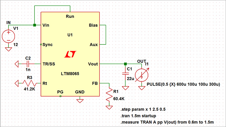
Open the previous download file and set the load current source settings to {X} with the maximum value as follows:
PULSE(0.5 {X} 600u 100u 100u 300u)
Also, write the ".step" command as follows.
.step param x 1 2.5 0.5
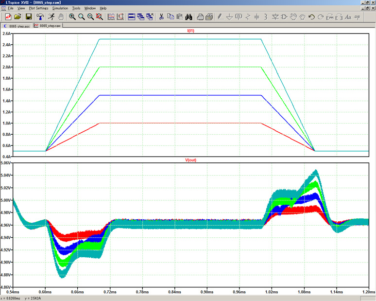
Finally, when we ran the simulation, we were able to confirm the results of the output voltage fluctuation in 0.5A steps (4 steps) from 1 to 2.5A as shown in the figure below.
If you open the Log file with "Ctrl" + "L" on the circuit diagram, you can read the maximum and minimum voltage values (Peak to Peak) when the step parameters are changed as shown in the figure below.
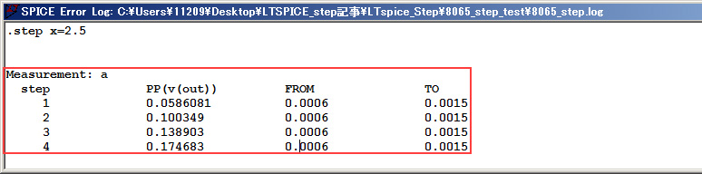
By combining ".step" and ".meas" in this way, it is possible to efficiently simulate a power supply IC.
LTspice demo file verified this time
After extracting the zip file to the same folder on a computer with LTspice installed, run LTspice to automatically start waveform display.
.step (RC circuit) simulation file
.step (LTM8065 circuit) simulation file
At the end
This time, the content was about ".step", but there are a wide variety of other commands available. We will continue to introduce various functions in the future, so please continue to support us.
We also hold regular LTspice seminars. You can learn the basic operation of LTspice, so we look forward to your participation.
Click here for LTspice seminar information
Click here for recommended articles/materials
List of articles: Let's use LTspice Series
LTspice FAQ: FAQ list
List of technical articles: technical articles
Manufacturer introduction page: Analog Devices, Inc.
Click here for recommended seminars/workshops
Inquiry
If you have any questions regarding this article, please contact us below.
Analog Devices Manufacturer Information Top
If you want to return to Analog Devices Manufacturer Information Top, please click below.