- Semiconductor BusinessHOME
- Products and Services of Macnica,Inc.
-
technical information

-
Events and Seminars
- Handling Manufacturer
- Support
- Inquiry
- Click here to purchase products
- Semiconductor business e-mail magazine registration
![]()
![]() Narrow down by specifying conditions
Narrow down by specifying conditions
現在2184件がヒットしています。check

Modern electronic devices can be powered by a variety of sources, including batteries, AC/DC adapters, USB, etc. Voltage monitoring and control by a microcontroller are required to prioritize these power sources and perform seamless switching.
Voltage monitoring and microcomputer control
To enable the supply of multiple power sources, it is necessary to take measures such as using diode OR to prevent each power source from becoming a load. Also, when incorporating a backup power source using a battery into the system, it is necessary to have hardware design that isolates the battery from the system so that it does not consume power, and to prioritize power supply switching.
When designing switching circuits like this one discretely, it often has problems such as not working properly.
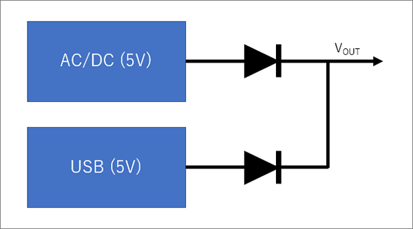
Diode OR circuit
For example, if a diode is used to switch between AC/DC and USB, the circuit configuration is very simple. However, a voltage drop and power loss due to the VF of the diode will occur. Also, if you want to use a battery as an auxiliary power source, you will need to implement a switching circuit or power supply voltage adjustment that supplies power only when there is no external power supply.
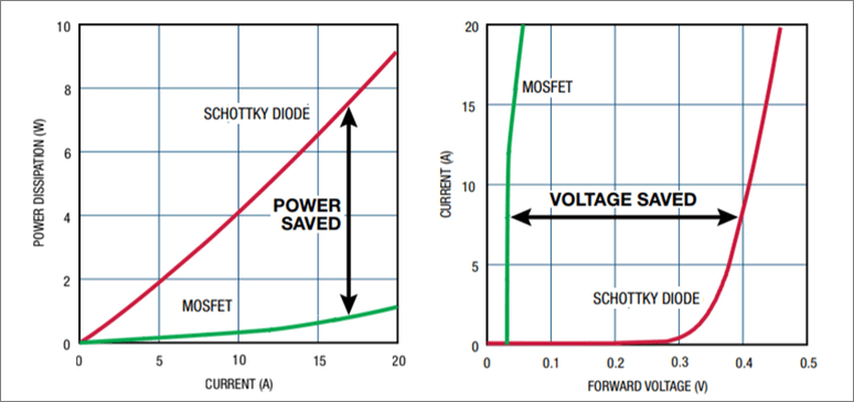
OR Circuit Using Power FET
By configuring an OR circuit using power FETs instead of diode ORs, it is possible to keep voltage drops and power losses small, as shown in Figure 2. However, a circuit to control the power FET is required, and when designed, it can be difficult to stabilize operation.
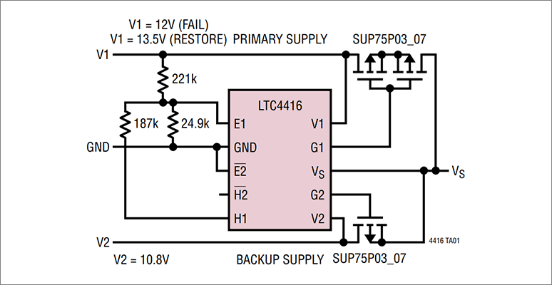
Power FET OR Circuit Using PowerPath Products
By using the Analog Devices PowerPath product LTC4416, it is possible to configure a stable power FET OR circuit. This makes it possible to stably switch between batteries and external power sources such as USB with low power consumption. Figure 3 shows a circuit configuration that switches between 13.5V and 10.8V power supplies supplied by the LTC4416.
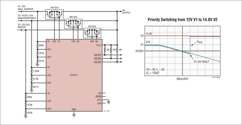
Prioritizable Power Path Products
In OR circuits using diode OR or power FETs, the power supply with the higher voltage has priority in supplying power to the circuit. However, in actual applications, it may not always be possible to set the voltage of the power supply you want to give priority to higher. In such cases, it is possible to configure the system by using a Power Path product called LTC4417, which allows you to set the power supply priority by pin assignment.
For example, if 12V is assigned to V1 as in Figure 4, the 12V supply will take priority even if 14.8V is also being supplied to V2. If the 12V supplied to V1 falls below the UVLO (Under Lockout Voltage), the circuit is configured to supply 14.8V as the second priority, as shown in the waveform diagram in Figure 4.
Recommended related information
Click here for recommended seminars/workshops
We list seminars that are currently accepting applications, so please apply for the ones you are interested in. We also have permanent on-demand seminars, so please take a look at those as well.
Click here for recommended articles/materials
Click here to purchase products
Click here for manufacturer site/other related links
Powerpass product information
LTC4417 Product Information
LTC4416 Product Information
Inquiry
If you have any questions regarding this article, please contact us below.
Analog Devices Manufacturer Information Top
To return to the Analog Devices manufacturer information top page, please click below.