- Semiconductor BusinessHOME
- Products and Services of Macnica,Inc.
-
technical information

-
Events and Seminars
- Handling Manufacturer
- Support
- Inquiry
- Click here to purchase products
- Semiconductor business e-mail magazine registration
![]()
![]() Narrow down by specifying conditions
Narrow down by specifying conditions
現在2174件がヒットしています。check

Let's try using LTspice from the previous article -Try changing the parameters with ".step" and try using LTspice from the previous article -How to check the maximum and minimum voltage values with".meas" uses the Spice command ".meas ” and “.step” were introduced.
This time we will introduce the ".save" and ".ic" commands. It can be used when you want to shorten the simulation execution time in the evaluation of switching regulators.
If you are just starting LTspice, we recommend that you look at the "basics" from the list below.
Let's use LTspice series list is here
Also, if you would like to see a video on how to write a basic circuit and how to execute it, there is an on-demand seminar that does not require you to enter personal information, so please take a look if you are interested. Detailed information about the seminar is also provided to those who fill in the questionnaire.
LTspice On-Demand Seminar - Function check with RC circuit -
Set initial state with ".ic" command
During transient analysis (.tran), the initial state of the operating point can be set using the ".ic" command. The syntax is:
.IC <voltage node or element current name> = <value>
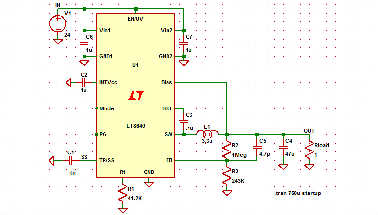
This time, we will explain using the JIG circuit of the switching regulator LT8640.
(* For details of LT8640, please refer to Let's use LTspice - Checking the operation of the DC/DC converter)
Run simulation
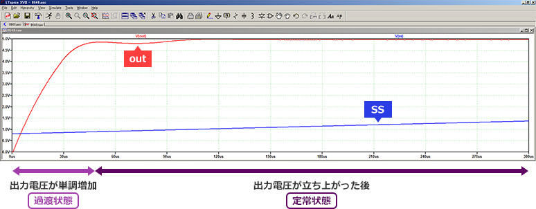
The JIG circuit in Figure 1 is used for transient analysis. You can observe the waveform from when the output voltage rises until it reaches a steady state. The points of measurement are the OUT and SS nodes.
Let's add an initial voltage value to the SS pin with the ".ic" command
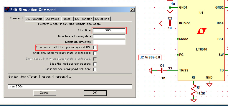
The SS pin is the pin that determines the rise time of the power supply voltage. Using the ".ic" command, I entered .IC V(SS)=0.8 as shown in Figure 3, and set the initial voltage of the SS pin to 0.8V.
As a result, the simulation time after reaching a steady state (5V output) is shortened, so I set "Stop Time" to 300usec. As a note at this time, when using the initial voltage command, it is necessary to uncheck "Start external DC supply voltage at 0V" in the simulation settings.
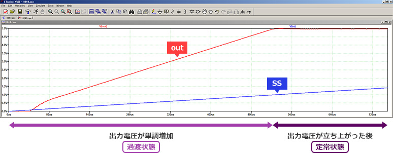
When we ran the simulation, we found that by applying an initial voltage to the SS pin, the soft-start function was disabled, and the output voltage rose quickly, shortening the simulation time.
By giving the initial voltage in this way, the number of calculations can be reduced, and as a result, the simulation time can be shortened.
Save only necessary data with ".save" command
Normally Spice saves simulation results for all node voltages, components and terminal currents. However, by using the ".save" command, you can save the simulation results for only the specified node voltage, component, and terminal current.
Syntax: .save<signal name>
Let's use the JIG circuit of the LT8640 to save only the waveform data of the OUT pin.
It's easy to use, just add the "save V(OUT)" syntax as shown in Figure 5.
In waveform simulation, only the waveform of the OUT terminal is displayed.
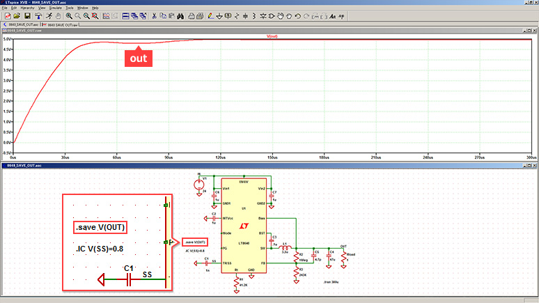
By limiting the nodes that store data, the number of accesses to the HDD is reduced, so not only the file capacity but also the writing time can be shortened. However, please note that you can only see the waveform of the specified node.
Check simulation time
I will also touch on how to check the simulation execution time.
Open SPICE Error Log (CTL+L) from Menu⇒View.
You can check the execution time from "Total elapsed time" in the file.

LTspice demo file verified this time
After extracting the zip file to the same folder on a computer with LTspice installed, run LTspice to automatically start waveform display.
.ic simulation file
.save simulation file
At the end
This time, we introduced ``.ic'' and ``.save'' with speed as a keyword.
We will continue to introduce various functions in the future, so please continue to support us.
We also hold regular LTspice seminars for beginners. You can learn the basic operation of LTspice, so please participate.
Click here for LTspice seminar information
Click here for recommended articles/materials
List of articles: Let's use LTspice Series
LTspice FAQ: FAQ list
List of technical articles: technical articles
Manufacturer introduction page: Analog Devices, Inc.
LTspice seminar information
Inquiry
If you have any questions regarding this article, please contact us below.
Analog Devices Manufacturer Information Top
If you want to return to Analog Devices Manufacturer Information Top, please click below.