- Semiconductor BusinessHOME
- Products and Services of Macnica,Inc.
-
technical information

-
Events and Seminars
- Handling Manufacturer
- Support
- Inquiry
- Click here to purchase products
- Semiconductor business e-mail magazine registration
![]()
![]() Narrow down by specifying conditions
Narrow down by specifying conditions
現在2168件がヒットしています。check

Have you ever tried to use LTspice and installed it, but have been frustrated in the middle of trying to enter while looking at a reference book, or have you not obtained the desired result due to an error? In order to solve such troubles, we will introduce "How to draw a circuit diagram in 5 steps".
If you are just starting LTspice, we recommend that you look at the "basics" from the list below.
Let's use LTspice series list is here
Also, if you would like to see a video on how to write a basic circuit and how to execute it, there is an on-demand seminar that does not require you to enter personal information, so please take a look if you are interested. Detailed information about the seminar is also provided to those who fill in the questionnaire.
LTspice On-Demand Seminar - Function check with RC circuit -
How to draw a schematic in 5 steps
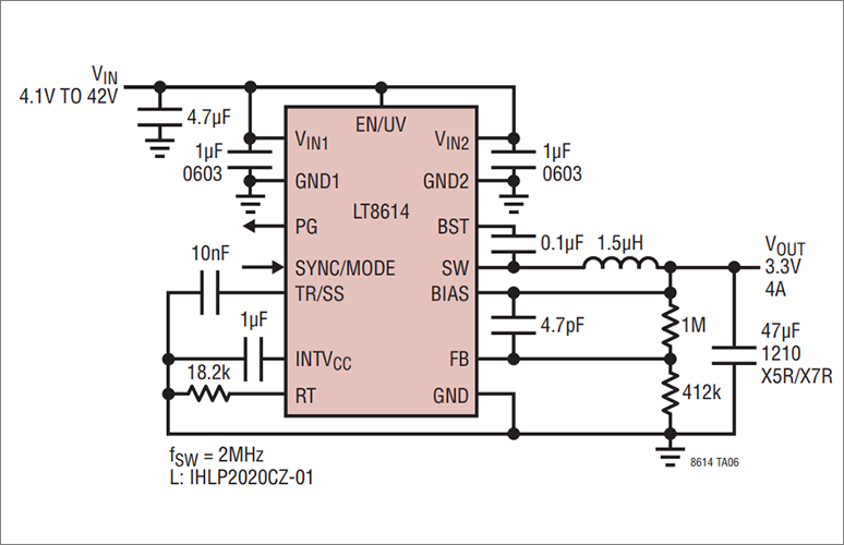
This time, I would like to make a circuit diagram using the switching regulator LT8614.
step 1
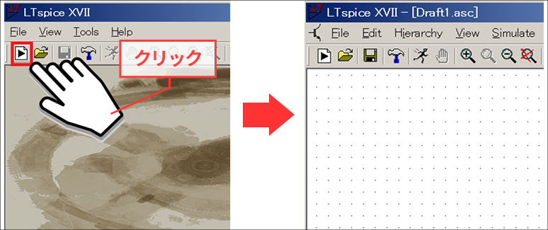
Click the LTspiceXVII icon on the desktop or select LTspiceXVII from the start menu to start LTspice.

step 2
Click New Schematics (framed in red) on the top left of the menu, or select New Schematics from the File menu. Then, the file for creating the schematic (Draft1.asc file) opens.
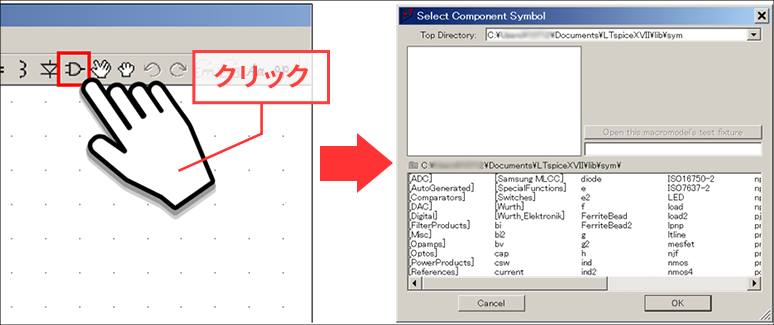
step 3
Click the menu component (framed in red) or press F2. Then, a menu for selecting a part called "Select Component Symbol" will be launched.
step 4
Enter the part name "LT8614" you want to simulate in the red frame part of the "Select Component Symbol" menu Fig. 4. The part will be automatically selected.
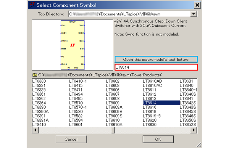
step 5
Finally, click the "Open this macromodel's test fixture" button in the blue frame in Figure 4.
Then you can get a circuit diagram with peripheral parts arranged.
*Some products do not have circuit diagrams. In that case, the "Open this macromodel's test fixture" button will not be active.
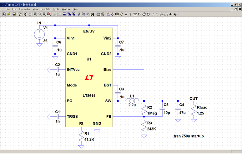
Run the simulation
By clicking "RUN" in this state to run the simulation, you can check the operation of the circuit.
This prepared circuit is called "JIG".
The JIG file this time is a circuit with a 5V output setting. If you need a schematic of the required input/output conditions (eg 3.3V output), check the product datasheet first.
After that, you can obtain the desired simulation result by modifying the JIG file according to the circuit diagram in the datasheet and executing it.
By using JIG files, you can make circuit diagrams more efficiently and reduce input errors.
We hope that you will make effective use of JIG files.
At the end
If you haven't used LTspice yet, please download LTspice from the link below!
Please try once.
Download LTspice here
We also hold regular LTspice seminars for beginners. You can learn the basic operation of LTspice, so please take a look.
Click here for LTspice seminar information
Click here for recommended articles/materials
List of articles: Let's use LTspice Series
LTspice FAQ: FAQ list
List of technical articles: technical articles
Manufacturer introduction page: Analog Devices, Inc.
Click here for recommended seminars/workshops
・Click here for information on analog circuit technology seminars
・LTspice On-Demand Seminar - Function check with RC circuit -
Inquiry
If you have any questions regarding this article, please contact us below.
Analog Devices Manufacturer Information Top
Analog Devices Manufacturer Information If you would like to return to the top page, please click below.