- Semiconductor BusinessHOME
- Products and Services of Macnica,Inc.
-
technical information

-
Events and Seminars
- Handling Manufacturer
- Support
- Inquiry
- Click here to purchase products
- Semiconductor business e-mail magazine registration
![]()
![]() Narrow down by specifying conditions
Narrow down by specifying conditions
現在2168件がヒットしています。check

Previous articleLet 's use LTspice - Let's create an original waveform with "behavior voltage source"! So, I introduced how to use Behavioral Voltage Sources (BV). I would like to introduce the controlled voltage source E (Voltage Dependent Voltage Source), which is the same voltage source this time.
If you are just starting LTspice, we recommend that you look at the "basics" from the list below.
Let's use LTspice series list is here
Also, if you would like to see a video on how to write a basic circuit and how to execute it, there is an on-demand seminar that does not require you to enter personal information, so please take a look if you are interested. Detailed information about the seminar is also provided to those who fill in the questionnaire.
LTspice On-Demand Seminar - Function check with RC circuit -
what can you do
I'll start by showing you an example of how to use it.
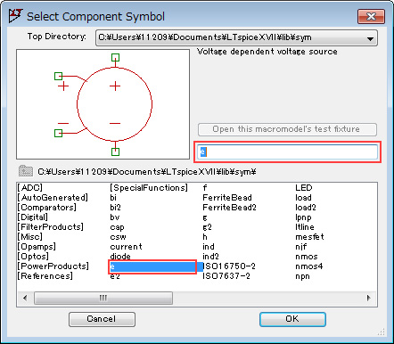
A controlled voltage source has four terminals. The two terminals on the left are input terminals (control terminals), and can output a voltage proportional to the input voltage difference. Therefore, if the constant of proportionality is greater than 1, it can be regarded as an amplifier, and if it is less than 1, it can be regarded as an attenuator.
Here, I would like to make a "10x amplifier".
First, select "e" in the "Select Component Symbole" dialog Box and place it on the schematic.
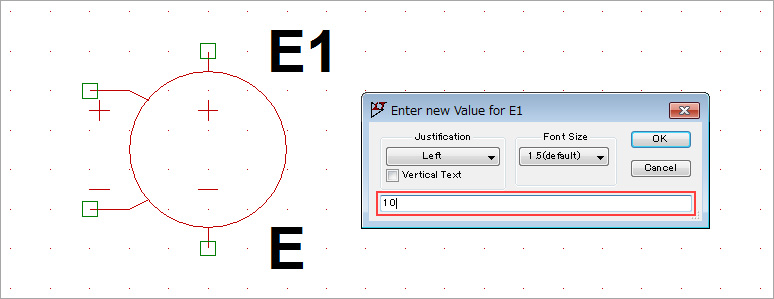
Next, fill in the constant of proportionality where "E" is. Change it to "10" because it is 10 times.
Move the cursor to the component (E1) and right-click, or right-click on the letter "E" to open the editor and enter the value in "Value".
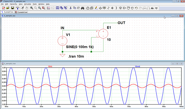
Next, wire the device as shown in Figure 3, apply a 1kHz, 100mVp-p sine wave, and observe the output waveform to confirm operation.
The waveform at the OUT terminal was amplified tenfold, and a waveform with an amplitude of 1Vp-p was observed. This demonstrates how easily amplifiers can be constructed.
Let's make an ideal operational amplifier with a voltage-controlled voltage source!
It turns out that a voltage controlled voltage source works as an amplifier. Here, I would like to make a simple comparison with an "op-amp", which is a representative IC for amplifiers.
As an example, as shown in Fig. 4, a 10-fold amplifier (non-inverting amplifier) is created using the high-precision operational amplifier IC "OP07." The voltage controlled voltage source also uses resistors to create a 10x non-inverting amplifier.
The gain of the voltage controlled voltage source was set to a very large value of 1T (10 to the 12th power). We will also focus on frequency specs as a comparatively easy-to-understand simulation example.
The frequency bandwidth (BW) of OP07 is 0.6MHz, and the frequency of the operational amplifier is not infinite, so signals larger than BW do not work as amplifiers.
Please refer to the following URL for the data sheet of OP07.
http://www.analog.com/media/en/technical-documentation/data-sheets/OP07.pdf
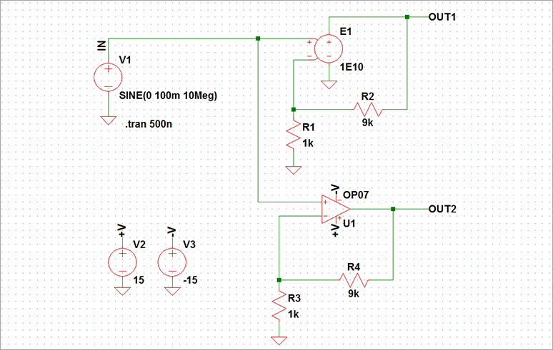
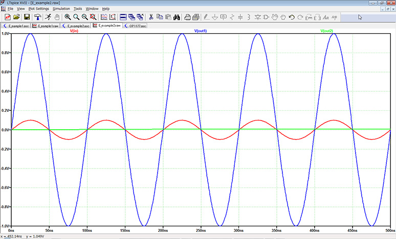
Figure 5 shows the simulation results.
Since the input signal was higher than 10MHz and BW, the output of OP07 (OUT2: green) was attenuated to almost 0V. On the other hand, the amplifier (OUT1: blue) created with a voltage-controlled voltage source produces a signal amplified by 10 times as expected.
I sometimes wonder which device model to use in simulation.
Especially in the design of amplifier circuits, operational amplifier ICs are often used as representative ICs. However, there are thousands of types of op amp ICs, so you may get confused about which model to use.
In addition, the specs of operational amplifiers are not ideal in reality, and there are limits such as open loop gain, frequency, input/output impedance, etc., and they are also affected by noise and temperature.
In such cases, using a voltage-controlled voltage source can be regarded as an ideal amplifier, so you can efficiently study basic circuit specifications without worrying about detailed specifications.
LTspice demo file verified this time
The two simulation files that were performed this time are stored. Please try!
At the end
This time, I introduced how to make an amplifier using a voltage-controlled voltage source!
In addition to the usage as an amplifier, there is also a usage defined by a transfer function (Laplace transform function) using a variable S.
I would like to introduce you again on another occasion.
If you haven't used LTspice yet, please download LTspice from the link below!
Please try once.
Download LTspice here
We also hold regular LTspice seminars for beginners. You can learn the basic operation of LTspice, so please participate.
Click here for LTspice seminar information
Click here for recommended articles/materials
List of articles: Let's use LTspice Series
LTspice FAQ: FAQ list
List of technical articles: technical articles
Manufacturer introduction page: Analog Devices, Inc.
Click here for recommended seminars/workshops
Inquiry
If you have any questions regarding this article, please contact us below.
Analog Devices Manufacturer Information Top
Analog Devices Manufacturer Information If you would like to return to the top page, please click below.