- Semiconductor BusinessHOME
- Products and Services of Macnica,Inc.
-
technical information

-
Events and Seminars
- Handling Manufacturer
- Support
- Inquiry
- Click here to purchase products
- Semiconductor business e-mail magazine registration
![]()
![]() Narrow down by specifying conditions
Narrow down by specifying conditions
現在2176件がヒットしています。check

The latest FPGAs are becoming more and more integrated, which increases the amount of power that can be handled by a single board, making thermal design more difficult.
How to calculate junction temperature
Until now, heat has been dealt with somehow during the case design stage, but from now on, it will be necessary to carry out some degree of heat calculations and component placement during the board design stage.
The junction temperature can be calculated using the following formula.
P: Power consumption (W)
T J: Junction temperature (℃)
T A: Ambient temperature (℃)
Θ JA: Thermal resistance of the package (℃/W)
For example, if the ambient temperature is 25°C, the thermal resistance of the FPGA package is 5°C/W, and the FPGA's power consumption is 10W, the junction temperature is TJ = 25°C + 5°C/W x 10W = 75°C.
Use the device at or below the absolute maximum junction temperature specified by the manufacturer.
Relationship between ambient temperature and junction temperature of FPGA
How to measure temperature
The junction temperature is calculated and the layout is determined so that devices with high temperatures do not interfere with each other. After the device layout is determined and the design is completed, the temperature is measured using a thermal camera or thermocouple. Then, it is confirmed whether the temperature rise is as estimated, or whether it is at a level that does not cause problems even if there is a difference.
In some cases, a thermal camera cannot be used if it is placed inside a housing, and the temperature can vary depending on how the thermocouple is attached. In such cases, measurements can be taken by making good use of a thermostatic chamber or stabilizing the thermocouple attachment method.
Measuring Temperature with the LTC2991
By using the Analog Devices LTC2991 product, it is possible to monitor temperature using a temperature measurement diode placed inside the FPGA or on the board, as shown in Figure 1.
This makes it possible to monitor temperature inside enclosures where a thermal camera cannot be placed, and enables stable temperature measurement without having to worry about stabilizing the thermocouple contact method.
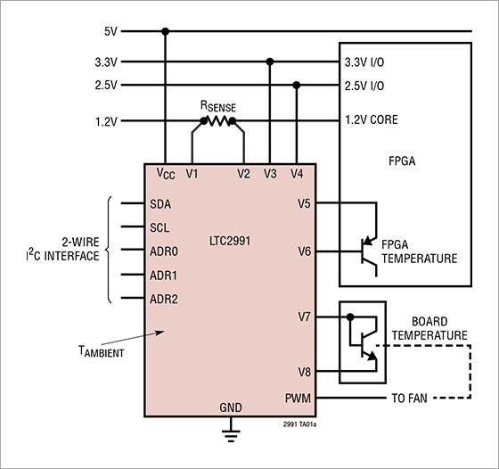
The usage in Figure 1 allows the following items to be monitored. First, by connecting a sense resistor (RSENSE) to the V1-V2 ports, it is possible to monitor the power consumption by monitoring the 1.2V core current. V3 and V4 monitor the voltage fluctuations of the 3.3V and 2.5V lines. By connecting the V5-V6 ports to a diode for measuring temperature inside the FPGA, it is possible to measure the junction temperature inside the FPGA. Furthermore, by placing a diode for measuring temperature on the board, it is possible to monitor the temperature on the board at the V7-V8 ports.
If the results of these measurements indicate a high temperature rise, it is possible to control the fan from a PWM signal and control the airflow.The temperature monitor function of the LTC2991 is useful for board evaluation, but by installing it on an actual mass-produced board, it is possible to obtain temperature logs, control the fan, and predict danger due to temperature, thereby safely shutting down the system and preventing accidents.
Recommended seminar
Click here for recommended articles/materials
・ Relationship between ambient temperature and junction temperature of FPGA
・ How to estimate FPGA power consumption
・ Types of FPGA power consumption and how to calculate it
Click here to purchase products
Inquiry
If you have any questions regarding this article, please contact us below.
Analog Devices Manufacturer Information Top
Analog Devices Manufacturer Information If you would like to return to the top page, please click below.