
![]()
![]() Narrow down by specifying conditions
Narrow down by specifying conditions
現在1888件がヒットしています。check


When designing a board that implements an FPGA, you probably check the power consumption of each device including the FPGA.
How do you check the power consumption of FPGA?
As mentioned in "FPGA power consumption types and calculation methods", FPGA power consumption consists of static + dynamic + I/O.
It also depends on the design (logic circuit).
Intel® for FPGA Users
We offer estimation tools: Early Power Estimator (EPE) and Intel® FPGA Power and Thermal Calculator (PTC).
This time, we will briefly explain the outline of EPE and PTC and the operation flow when estimating them.
EPE/Intel® FPGA PTC Overview
EPE and Intel FPGA PTC are used to estimate power consumption relatively early in the design process.
After completing your design, we recommend that you analyze it using the Quartus® Prime Power Analyzer.
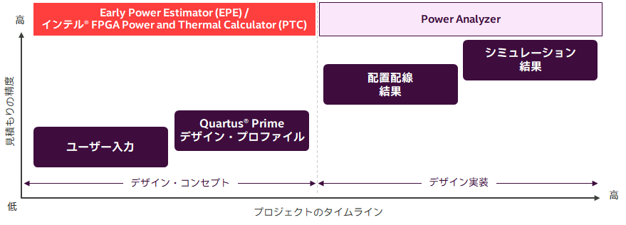
EPE and Intel® PTC are used depending on the FPGA being developed as shown in the table below.
|
Early Power Estimator (EPE) |
Intel® FPGA Power and Thermal Calculator (PTC) |
||||||||||
| Target FPGA |
Stratix® series (excluding Stratix® 10) Arria® series Cyclone® series MAX® 10、MAX® V、MAX® II |
Agilex® FPGA Series Startix® 10 FPGA |
|||||||||
| tools to use |
Get the spreadsheet from the manufacturer's webpage |
Use features integrated in Quartus® Prime Pro Edition or Download & Install Standalone Intel FPGA PTC |
|||||||||
|
Information to enter |
- Resource usage (estimated number if the design is not completed) - Input clock requirements and toggle rate ・Environmental conditions etc.
|
||||||||||
|
Quartus® Prime compile information Necessary when reflecting file format |
.csv |
.qptc |
|||||||||
|
Operation flow |
|||||||||||
how to get
Get EPE
It is available on the Intel® FPGA website Early Power Estimator (EPE) and Power Analyzer.
Download the EPE for your target FPGA family. A user guide for EPE is also available.
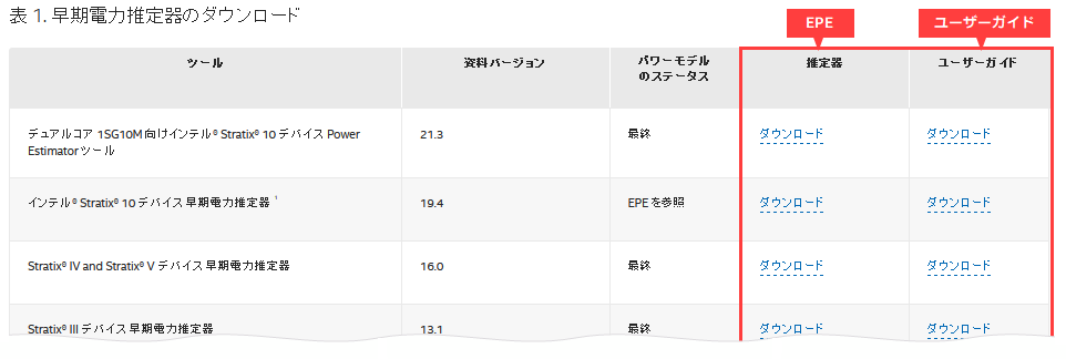
[Notes] If you cannot download EPE on the Japanese page, please select "English" from the language switching menu at the top right of the page to switch to the English page before using.

Get Intel® FPGA PTC
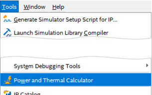
Intel® FPGA PTC is a standard feature in Quartus® Prime Pro Edition. If Quartus® Prime Pro Edition is installed,you can launch and use the GUI from the Tools menu.
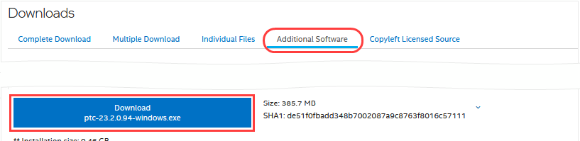
Alternatively,you can use Intel FPGA PTC as a standalone version. In that case, please download and install it from the FPGA Software Download Center.
The user guide is available at the link below.
EPE operation flow
As shown in the overview diagram, resource information entered into the EPE is handled differently depending on how complete the FPGA design is.
● If the design is incomplete ➡User input
|
1 User manually enters resource information into EPE |
2 User manually enters environmental conditions into EPE |
3 Check the estimate result |
recommendation!
● If the design is complete & can be compiled ➡ Quartus Prime Design Profile
|
1 With Quartus ® Prime コンパイル実行 |
2 With Quartus ® Prime Generate csv file |
3 Import .csv to EPE |
4 Check the estimate result |
EPE: User input
1. User manually enters resource information into EPE
When you open the downloaded EPE, you will see a spreadsheet as shown below.
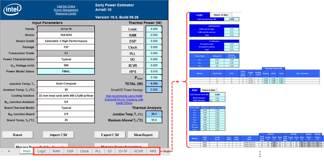
There are fields at the bottom of the spreadsheet where you manually enter the expected resource information for the FPGA in each tab. (Items on the tab vary depending on the target FPGA.)
|
Logic: Logic PLL: PLL (Phase-Lock-Loop circuit) HPS: Hard Processor System (SoC) |
RAM: Built-in memory IO : I/O |
DSP: DSP block IO-IP: I/O interface IP |
Clock: Clock XCVR: Transceiver |
For more information, please refer to the tooltip comments in the appropriate item cell in the spreadsheet or the Early Power Estimator user guide for each family.
2. User manually enters environmental conditions into EPE
Specify the environmental conditions in the Input Parameters area of the Main tab.
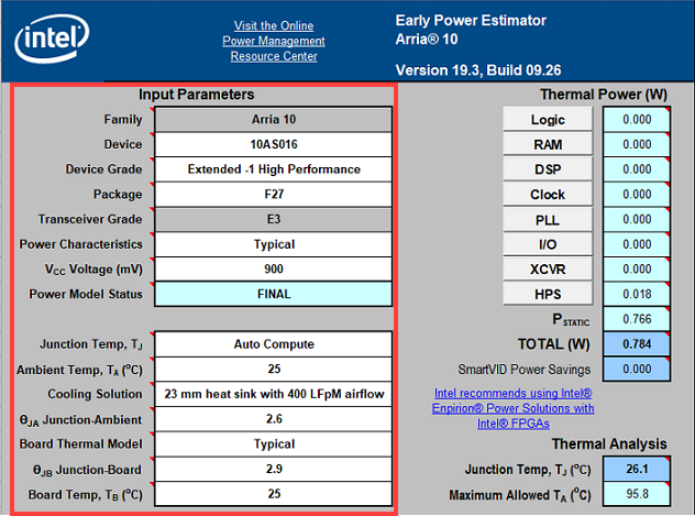
| Family | Select device family | Junction Temp, TJ | Choose whether junction temperature (T J) is automatically calculated or entered by the user. |
| Device | Select device model number | Ambient Temp, TA | Enter the temperature of the atmosphere to cool the device |
| Device Grade | Choose your combination of operating temperature, speed grade, and power options | Cooling Solution | Select relevant airflow cooling solutions |
| Package | Select device package | ΘJA Junction-Ambient | Enter Junction-Ambient value |
| Transceiver Grade | Choose a standard or theoretical worst-case silicon process | Board Thermal Model | Select board type for thermal analysis |
| Power Characteristics | Select Typical or Maximum | ΘJB Junction-Board | Enter Junction-Board value |
| VCC Voltage | Select the V CC power rail for your device | Board Temp, TB | Enter the board temperature to use in thermal calculations when entering a custom or standard Board Thermal Model. |
| Power Model Status | Shows whether the device power model is in preliminary or final state | ||
*Item contents vary depending on device family.
*For items not listed in the table above, hover over the corresponding item cell in the spreadsheet and refer to the comment in the tooltip that appears.
3. Check the estimate result
The Thermal Power and Thermal Analysis areas of the Main tab display the estimated results calculated from the conditions entered by the user.
[Notes] These calculation results are not specifications. Use it as an "estimate" for power consumption.
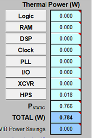
The Thermal Power area displays the estimated power consumed within the device.
Total power consumption is the sum of thermal power for all resources used by the device, including maximum power from standby power and dynamic power.
[Notes]The total thermal power dissipation includes only the thermal components of the I/O section and does not include external thermal power dissipation such as reference voltage termination resistors.
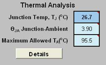
The Thermal Analysis area displays values for junction temperature (TJ), total junction-to-ambient thermal resistance (θJA), and maximum allowable ambient temperature (TA).
The above is the operation flow for EPE based on user input.
EPE: Quartus Prime Design Profile
1. Compile with Quartus® Prime
Once the project is designed and constrained, compile it to completion.
Processing menu ⇒ Start Compilation
2. Generate csv file in Quartus® Prime
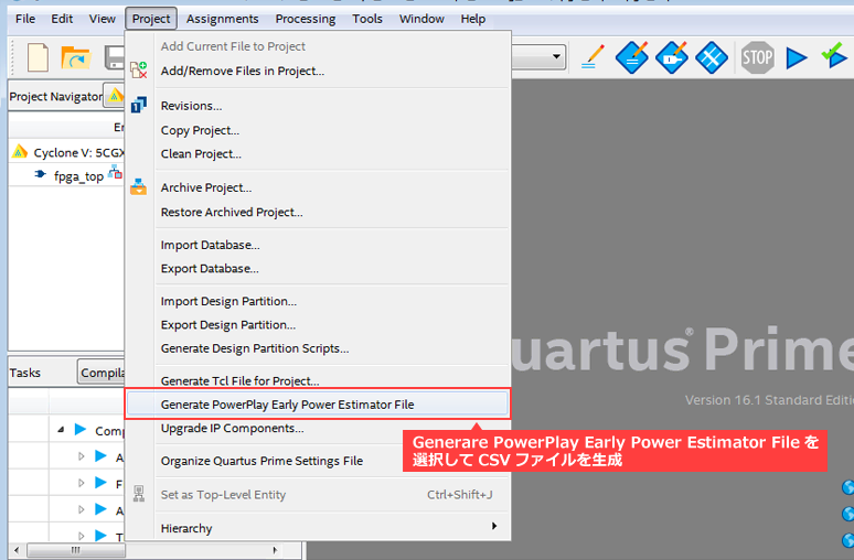
Generates a CSV file for EPE based on the environment set for the compiled project design and the compilation results.
Project menu ⇒ Generate PowerPlay Early Power Estimator File
(File name: *_early_pwr.csv)
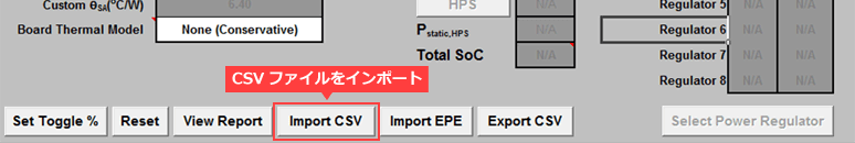
3. Import .csv to EPE
Import the *_early_pwr.csv file generated by Quartus® Prime into EPE.
4. Check the estimate result
The Thermal Power and Thermal Analysis areas of the Main tab display the estimated results calculated from the conditions entered by the user.
[Notes] These calculation results are not specifications. Use it as an "estimate" for power consumption.
The Thermal Power areadisplays the estimated power consumed within the device.
Total power consumption is the sum of thermal power for all resources used by the device, including maximum power from standby power and dynamic power.
[Notes]The total thermal power dissipation includes only the thermal components of the I/O section and does not include external thermal power dissipation such as reference voltage termination resistors.
The Thermal Analysis areadisplays values for junction temperature (TJ), total junction-to-ambient thermal resistance (θJA), and maximum allowable ambient temperature (TA).
The above is the operation flow using the Quartus Prime design profile in EPE.
Intel® FPGA PTC Operation Flow
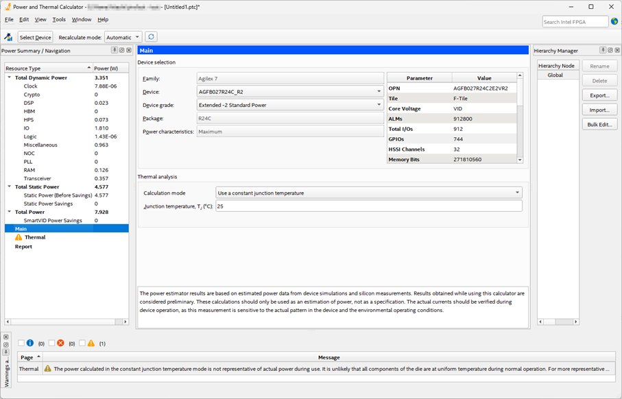
When you start "Power and Thermal Calculator" from the Tools menu on Quartus® Prime Pro Edition, the GUI shown below will be displayed.
the overview diagram, resource information entered into PTC is handled differently depending on how complete the FPGA design is.As shown in
● If the design is incomplete ➡User input
|
1 User manually enters resource information into PTC |
2 User manually enters environmental conditions into PTC |
3 Check the estimate result |
recommendation!
● If the design is complete & can be compiled ➡ Quartus Prime Design Profile
|
1 Quartus® Prime コンパイル実行 |
2 Quartus® Prime Generate QPTC file |
3 Import .qptc to PTC |
4 Check the estimate result |
PTC: User input
1. User manually enters resource information into PTC
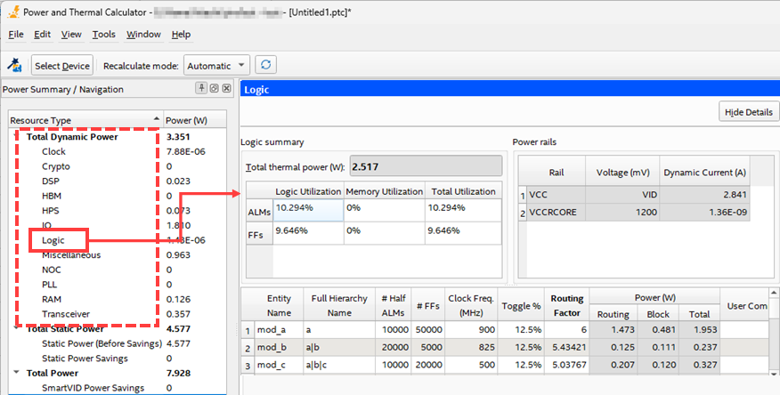
In the Resource Summary / Navigation window, select each item from Total Dynamic Power in Resource Type and manually enter the resource information expected by the FPGA. (Items on the tab vary depending on the target FPGA.)
|
Clock: Clock Crypto: Crypto block DSP: DSP block |
HBM : High Bandwidth Memory HPS: Hard Processor System (SoC) IO : I/O |
Logic: Logic NOC: Memory Network on Chip PLL: PLL (Phase-Lock-Loop circuit) |
RAM: Built-in memory Transceiver: transceiver |
For more information, please refer to the Intel® FPGA Power and Thermal Calculator User Guide.
2. User manually enters environmental conditions into PTC
Select Main from Resource Type in the Resource Summary / Navigation window and specify the environmental conditions.
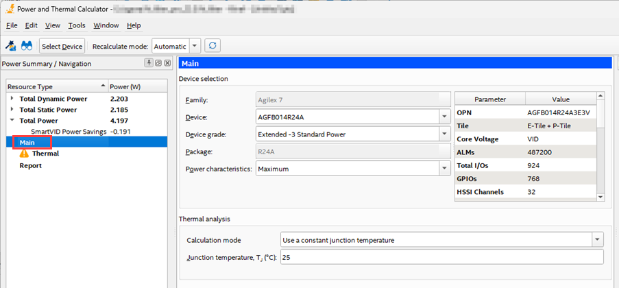
| Family |
Displays selected device family when starting PTC (If you start PTC after setting a project, it will be set automatically.) |
Calculation mode | Specify the calculation mode of the thermal analysis solver to use |
| Device | Select device model number | Junction temperature, TJ (°C) | Specify junction temperature for all dies in the package |
| Device Grade | Select the combination of operating temperature, speed grade, and power options you want to use | ||
| Package | Select device package | ||
| Power characteristics | Select Typical or Maximum | ||
| VCC Voltage (mV) |
*Displays Stratix 10 PTC only |
||
*Item contents vary depending on device family.
*For details, please refer to the Intel® FPGA Power and Thermal Calculator User Guide
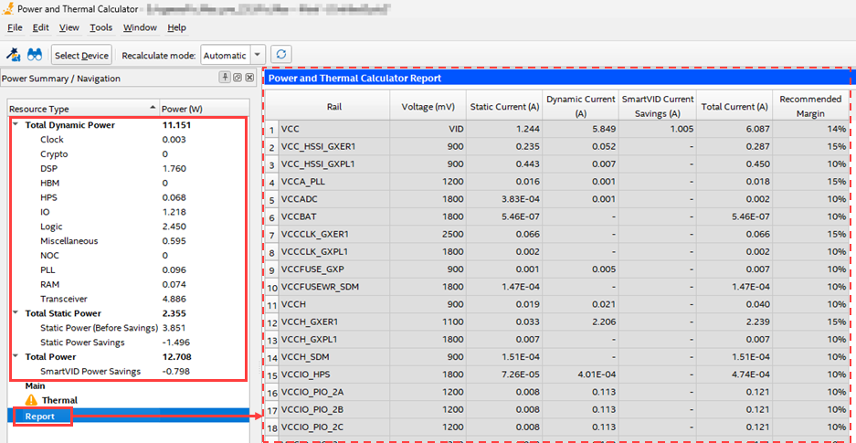
3. Check the estimate result
The calculated power consumption for each resource is displayed under Resource Type in the Resource Summary / Navigation window.
The Report also displays the current per power rail calculated by PTC.
The above is the operation flow using PTC user input.
PTC: Quartus Prime Design Profile
1. Compile with Quartus® Prime Pro Edition
Once the project is designed and constrained, compile it to completion.
Processing menu ⇒ Start Compilation
2. Generate QPTC files with Quartus® Prime Pro Edition
When you run Power Analyzer in Quartus® Prime Pro Edition, it generates a QPTC file for PTC based on the environment settings and compilation results for the compiled project design.
Processing Menu ⇒ Start ⇒ Start Power Analyzer
(File name: <project_revision_name>.qptc)
3. Import .qptc to PTC
When you start PTC with the project open, the window shown below will be displayed, and when you click the OK button, the .qptc in the project will be automatically imported.
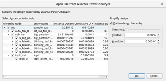
You can also import .qptc from the File menu ⇒ Open in PTC.
4. Check the estimate result
The calculated power consumption for each resource is displayed under Resource Type in the Resource Summary / Navigation window.
The Report also displays the current per power rail calculated by PTC.
The above is the operation flow using the Quartus Prime design profile in PTC.
At the end
EPE and PTC results are approximations of the FPGA's power and thermal characteristics and are not exact specifications of the actual power consumed during device operation. In addition, input information is extremely important when estimating power consumption, as the input factors (resources, toggle rate, temperature, etc.) greatly affect the results.
Both EPE and PTC can be easily estimated using the Quartus® Prime design profile, but once you are able to compile your design, switch to the Quartus® Prime Power Analyzer for more accurate power analysis. Get your results.
Actual power consumption is affected by the device and design input signals, so be sure to check the actual power consumption while the device is operating.
Click here for recommended articles/materials
FPGAの消費電力の種類と計算方法
FPGA の周囲温度とジャンクション温度との関係
超初心者向けのアナログ回路 Enpirion® 編 第2回 FPGA の消費電力は?