- Semiconductor BusinessHOME
- Products and Services of Macnica,Inc.
-
technical information

-
Events and Seminars
- Handling Manufacturer
- Support
- Inquiry
- Click here to purchase products
- Semiconductor business e-mail magazine registration
![]()
![]() Narrow down by specifying conditions
Narrow down by specifying conditions
現在2168件がヒットしています。check

In the previous article Let's use LTspice - Let's make an amplifier with a voltage-controlled voltage source, we introduced how to use a controlled voltage source E (VoltageDependent Voltage Source). This time, I would like to use the Laplace function to create an op-amp model (amplifier) in a different way from last time.
If you are just starting LTspice, we recommend that you look at the "basics" from the list below.
Let's use LTspice series list is here
Also, if you would like to see a video on how to write a basic circuit and how to execute it, there is an on-demand seminar that does not require you to enter personal information, so please take a look if you are interested. Detailed information about the seminar is also provided to those who fill in the questionnaire.
LTspice On-Demand Seminar - Function check with RC circuit -
What is Laplace?
In LTspice's controlled voltage source (E), you can use Laplace function (Laplace function: transfer function using variable S). This function makes it possible to create various equivalent models by creating differential equations for the voltage source.
If you have studied electrical or electronic engineering, you have probably heard words such as the Laplace transform. For more information, please refer to reference books.
Let's make a first-order low-pass filter with Laplace!
I would like to explain how to use it while creating a first-order low-pass filter model with the Laplace function.
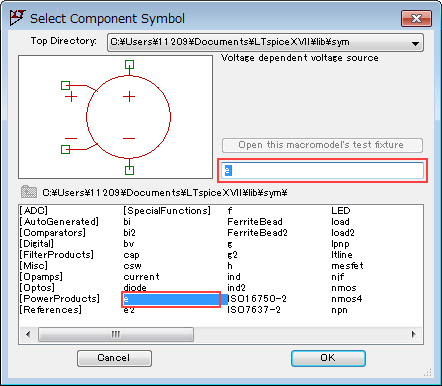
As in the previous article, use the voltage-controlled model 'e' and enter the Laplace function in the "Value" part.
Place the cursor on the component (E1) and right-click, or right-click on the letter "E" to open the editor, so the "Value" tag will open.
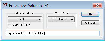
The transfer function of a first-order low-pass filter is expressed as "1/(1+TS)" because it is a first-order lag element.
Here, set the cutoff frequency fc=1.59kHz. Therefore, we can calculate "T=1/(2*pi*fc)=100e-6" and enter "Laplace = 1/(1+100e-6*s)" in the formula.
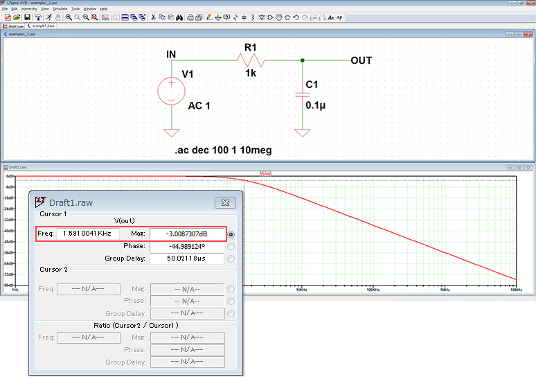
The circuit diagram was set as shown in Fig. 3, and when the frequency characteristics were confirmed by AC analysis, a cutoff frequency of approximately 1.59Hz was observed!
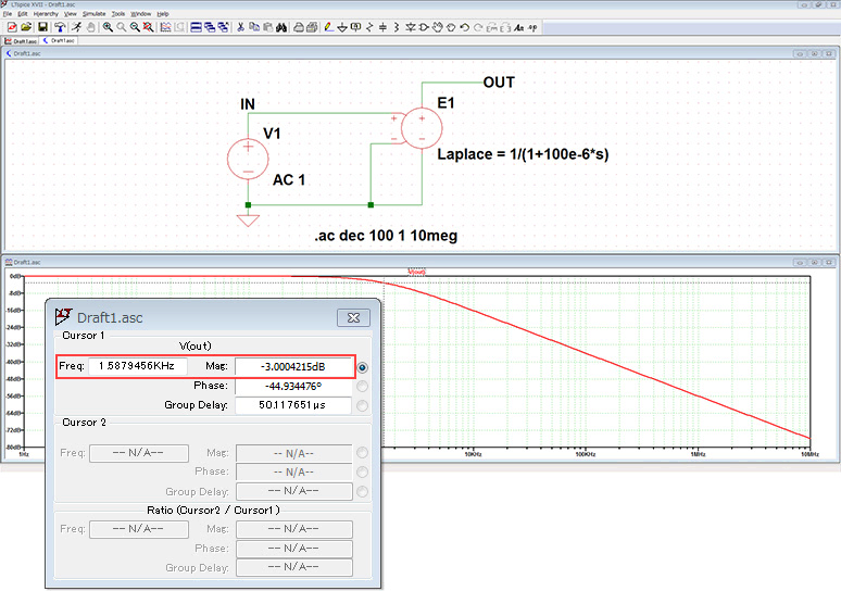
Figure 4 shows the results of creating a first-order low-pass filter with a cutoff frequency of fc=1.59Hz using the resistor (R) and capacitor (C) components.
In this way, using Laplace functional notation, you can use mathematical models to perform simulations instead of building them out of parts.
Let's make an op amp model with Laplace!
Finally, I would like to create an op amp model using Laplace.
For specifications, consider a model with an open loop gain of 100dB (10^5 times) and a unity gain of 10MHz (GB product = 10MHz). A simple amplifier model that sets only the gain and bandwidth without considering specifications such as offset.
The transfer function (G) of the operational amplifier can be expressed as "G=Vout/Vin=A/(1+TS)" from the amplification factor (A) and the first-order delay element (1+TS). A is 100 dB, so let's say 1e5. Also, T is obtained from GBW. Cutoff frequency fc can be calculated as GBW/A=10MHz/1e5=100Hz, so finally T=1/(2*pi*Fc)=0.00159.
Finally, using the Laplace function, enter "Laplace = 1e5/(1+0.00159*s)" into the formula and run the simulation in Figure 5.
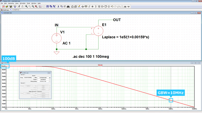
As shown in the AC analysis results, we were able to easily create a simple operational amplifier with GBW=10MHz.
LTspice demo file verified this time
The simulation performed this time is stored. Please try!
At the end
This time, I used the Laplace function to create filters and operational amplifiers.
The Laplace function can be used not only for amplifier and filter design, but also for control system design, motor modeling, and analysis that combines electronic circuits and other things, so please make use of it.
If you haven't used LTspice yet, please download LTspice from the link below!
Please try once.
Download LTspice here
We also hold regular LTspice seminars for beginners. You can learn the basic operation of LTspice, so please participate.
Click here for LTspice seminar information
Click here for recommended articles/materials
List of articles: Let's use LTspice Series
LTspice FAQ: FAQ list
List of technical articles: technical articles
Manufacturer introduction page: Analog Devices, Inc.
Click here for recommended seminars/workshops
Inquiry
If you have any questions regarding this article, please contact us below.
Analog Devices Manufacturer Information Top
If you want to return to Analog Devices Manufacturer Information Top, please click below.