- Semiconductor BusinessHOME
- Products and Services of Macnica,Inc.
-
technical information

-
Events and Seminars
- Handling Manufacturer
- Support
- Inquiry
- Click here to purchase products
- Semiconductor business e-mail magazine registration
![]()
![]() Narrow down by specifying conditions
Narrow down by specifying conditions
現在2154件がヒットしています。check

In the previous article Let's use LTspice - Let's create an op-amp model with Laplace, we introduced an example of creating an amplifier using a voltage-controlled voltage source.
This time, I would like to introduce how to make the created circuit diagram into components (hierarchical).
If your schematic becomes complex, you can improve overall readability by breaking it down into components. Also, the created components can be reused in other projects.
If you are just starting LTspice, we recommend that you look at the "basics" from the list below.
Let's use LTspice series list is here
Also, if you would like to see a video on how to write a basic circuit and how to execute it, there is an on-demand seminar that does not require you to enter personal information, so please take a look if you are interested. Detailed information about the seminar is also provided to those who fill in the questionnaire.
LTspice On-Demand Seminar - Function check with RC circuit -
Component (hierarchical) method
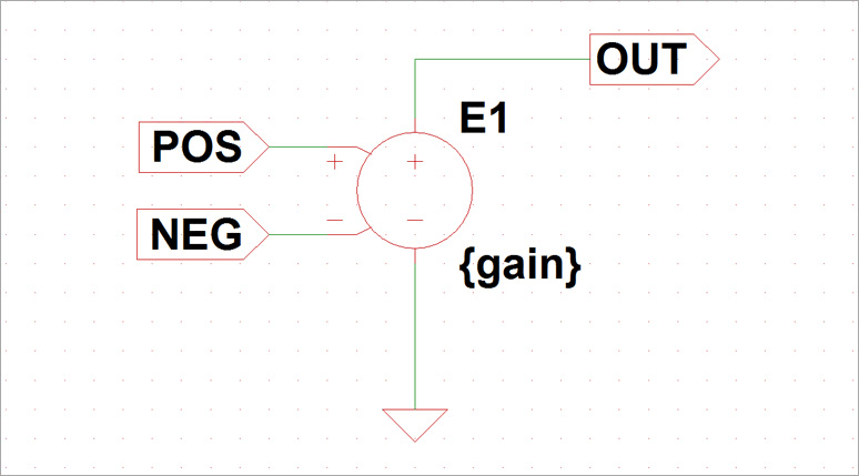
This time, we will explain how to make components using the circuit diagram of an amplifier that uses a controlled voltage source as an example. First create the circuit in Figure 1 in a new schematic.
For how to use a controlled voltage source, please refer to the article Let's use LTspice - Let's make an amplifier with a voltage controlled voltage source. The point here is to set the variable “gain” in the expression of the control voltage source so that the value can be changed arbitrarily after componentization. The variable name is "gain", but there is no problem with other variable names.
Also, label the input/output terminals. Here, the + input terminal is "POS", the - input terminal is "NEG", and the output terminal is "OUT".
Next, componentize the created schematic.
From the Edit menu, execute “Hierarchy → Open this Sheet's Symbol → Couldn't find … [YES]”, and the symbol will be automatically created as shown in Figure 2.
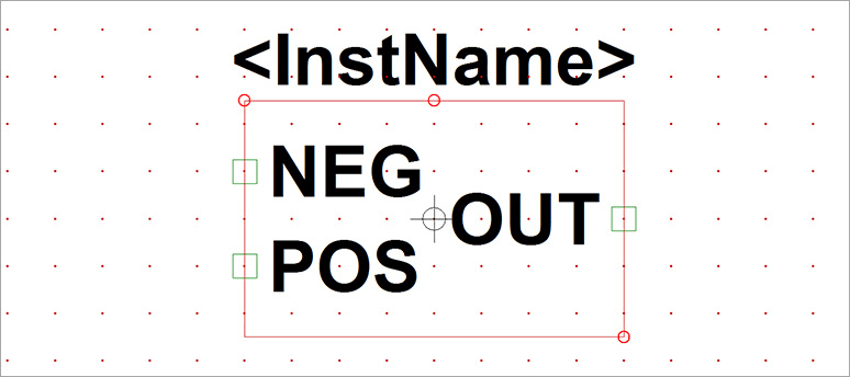
You can edit the shape by using “Draw”, “Delete”, etc. in the menu.
This time, I edited it in the shape of an operational amplifier as shown in Figure 3.
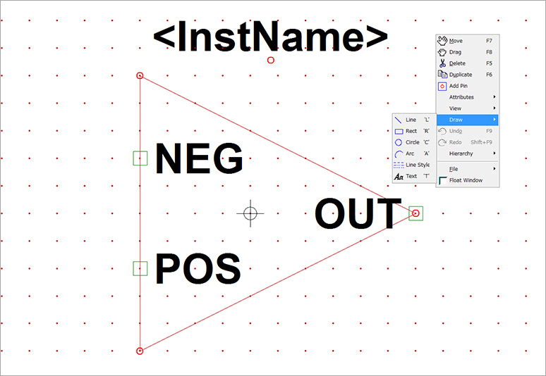
The above is how to convert a schematic into components. Next, let's check the operation of the created component.
Let's use the created component
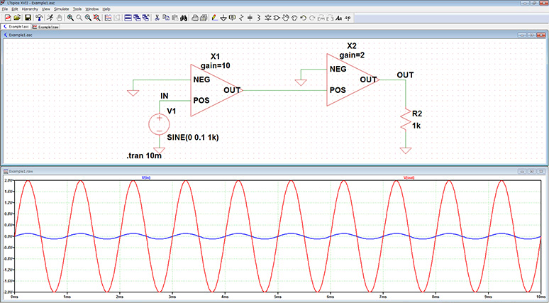
We will create a 20x amplification circuit using two of the created components.
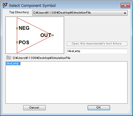
Launch a new “New Schematic” and select the created component in the “Select Component Symbole” dialog Box.
Next, set the gain of the component.
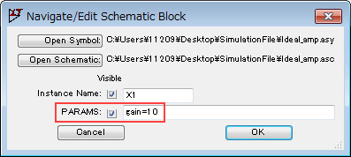
Right-click on the component to bring up the “Navigate/Edit Schematic Block” dialog Box shown in Figure 5. Set the “PARAM” item to “gain=10”.
Similarly, another component is set to “gain=2”.
Finally, I created the circuit as shown in Fig. 6, and when I checked the operation, I was able to observe a signal that was 20 times the input signal (IN) at the output (OUT) terminal.
LTspice demo file verified this time
The simulation file executed this time is stored. Please try!
At the end
This time, I introduced how to make a circuit diagram into components (hierarchy). Not only does it improve the readability of the schematic, it also makes it possible to use the same circuit block multiple times. It's a very useful feature, so please take advantage of it!
If you haven't used LTspice yet, please download LTspice from the link below!
Please try once.
Download LTspice here
We also hold regular LTspice seminars for beginners. You can learn the basic operation of LTspice, so please participate.
Click here for LTspice seminar information
Click here for recommended articles/materials
List of articles: Let's use LTspice Series
LTspice FAQ: FAQ list
List of technical articles: technical articles
Manufacturer introduction page: Analog Devices, Inc.
Click here for recommended seminars/workshops
Inquiry
If you have any questions regarding this article, please contact us below.
Analog Devices Manufacturer Information Top
If you want to return to Analog Devices Manufacturer Information Top, please click below.