- Semiconductor BusinessHOME
- Products and Services of Macnica,Inc.
-
technical information

-
Events and Seminars
- Handling Manufacturer
- Support
- Inquiry
- Click here to purchase products
- Semiconductor business e-mail magazine registration
![]()
![]() Narrow down by specifying conditions
Narrow down by specifying conditions
現在2176件がヒットしています。check


hello.
My name is Hanako Altera and I provide technical support for Altera® FPGA products at Macnica.

When functionally simulating a design for an Altera® FPGA, an EDA simulator is used.
This time, we will introduce the convenient "NativeLink Simulation" for this simulation work.
This is Hanako's recommended flow!
Here, we will introduce an example using Questa* - Altera® FPGA Edition (hereinafter referred to as Questa- AFE, including Starter Edition) as a simulation tool.
What is NativeLink
Running EDA tools from Quartus® Prime is called NativeLink.
For example, when you click the Quartus® Prime menu, the following process is automatically performed: <Questa - AFE is launched, compilation and loading required for simulation are performed, and the simulation results are displayed in the waveform window>.
This flow is highly recommended not only for those who do not understand the GUI operation of Questa - AFE but also for those who want to improve the efficiency of their operations.
Hanako's Tweet
If your design contains IP (Intellectual Property) modules created with the IP Catalog or Platform Designer,
How do I know which simulation library to use for my simulation tool?
NativeLink simulation eliminates such worries!
This method will automatically load all the simulation libraries needed to functionally simulate the IP module.
This is especially useful for designs that use multiple different IP modules.
NativeLink Supported Environments
The environments in which NativeLink can be used are shown below.
| Table 1. NativeLink supported environment(*1) | |
| handle Quartus Prime |
Quartus® Prime Standard Edition / Quartus® Prime Lite Edition * Pro Edition is not supported. (For the Pro Edition, please see this content.) |
|
to support |
Aldec Active-HDL / Riviera-PRO Cadence Xcelium* Logic Simulation Siemens EDA Questa Sim Siemens EDA Questa - Altera® FPGA Edition Synopsys VCS |
Note 1: All schematic designs (.bdf) must be converted to HDL.
<Reference FAQ> Q: I want to simulate a design with a schematic in ModelSim, but it doesn't work.
Note 2: For the supported versions of each EDA tool, please refer to the release notes for each version of Quartus® Prime you are using.
Set up your environment
Set up your environment to run NativeLink.
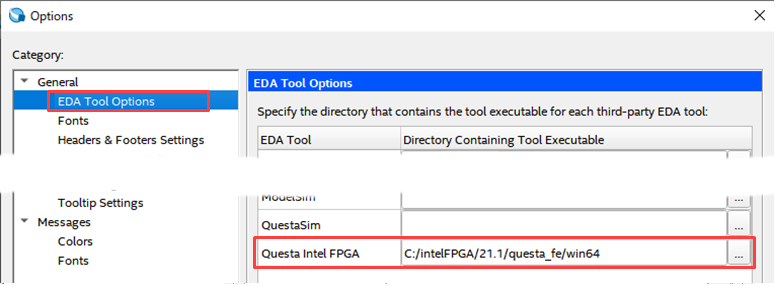
- In Quartus® Prime, under the Tools menu ➤ Options ➤ General, click EDA Tool Options.
- Click the [...] button on the right side of the Questa Altera FPGA row and specify the absolute path to the folder where the executable program is saved.
If you are using Windows OS, please specify the win64 folder where questasim.exe is saved.
work flow
- Register all designs that need to be compiled in Quartus® Prime in a Quartus® Prime project.
Project menu ➤ Add/Remove Files in Project
* In the case of designs that include IP, be sure to check Hanako 's Point ♪①/Hanako's Point♪②.
* If the design does not include IP,proceed to 2.

Hanako's point ♪ ①
If IP created inPlatform Designer is included
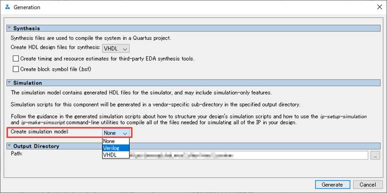
Enable the "Create simulation model option" in the Generation dialog Box that pops up when you run Generate HDL.
Clicking the Generate (or Generate HDL) button after selecting the language to generate will also generate a functional model for your simulation tool.
Hanako's point ♪ ②
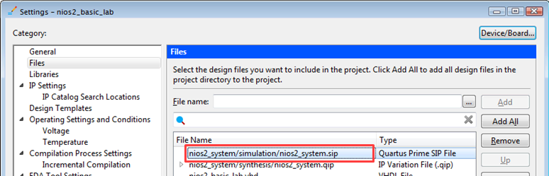
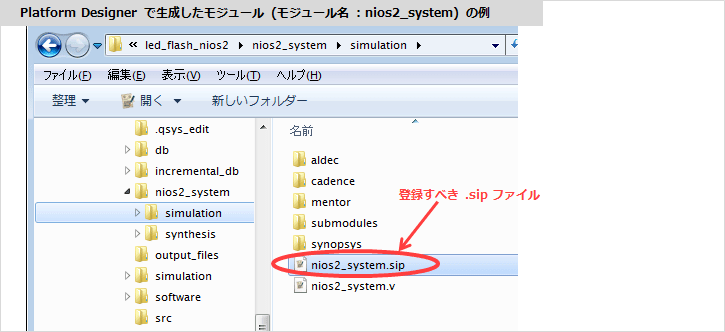
"IP module created with Platform Designer" or "IP module selected from IP Catalog and created with Platform Designer GUI base"
If you include it in your design, be sure to register <ip_name>.sip as well as <ip_name>.qip using the following menu in Quartus® Prime.
Project Menu ➤ Add/Remove Files in Project
* "IP module created by MegaWizard Plug-In Manager based GUI by selecting IP from IP Catalog" does not generate *.sip file.
Register only the *.qip file in the project.
<Related FAQ> What kind of file is a .sip file?
Where the .sip file is generated depends on whether you created the IP module in IP Catalog / Platform Designer.
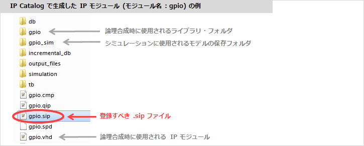
[IP module created with IP Catalog]
A .sip file will be generated in the folder where the <ip_name>.v (or .vhd) was generated.
(* It is in the folder in the same hierarchy as the <ip_name>_sim folder.)
A .sip file will be generated in the <ip_name>. folder ➤ simulation folder.
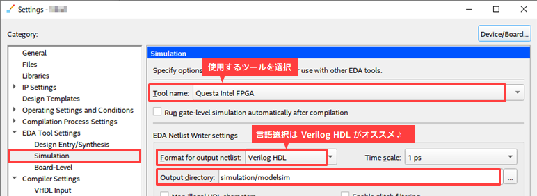
2. Select Assignments ➤ Settings ➤ EDA Tool Settings ➤ Simulation and set the following items in the EDA Netlist Writer settings.
・ Tool name: Questa Altera FPGA (※ Select this for Starter Edition as well)
・ Format for output netlist : Verilog HDL (reference: Hanako's point♪③)
・ Output directory: simulation/modelsim (default is recommended)
Hanako's point ♪ ③
Even if the simulation model and testbench when creating the IP are in VHDL, it is recommended to select Verilog HDL for this option.
This choice of language affects the vsim -L command in the NativeLink executable script.
In recent IP, even if VHDL is specified for the language selection of the simulation model, the lower model is often configured in SystemVeriog, which inevitably requires a simulation library for Verilog HDL. In that case, it is necessary to specify all libraries for Verilog HDL with the vsim -L command, so use Verilog HDL for Format for output netlist even if the model is generated in VHDL.
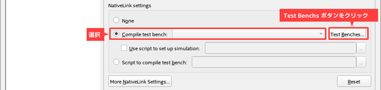
3. In the NativeLink settings, register the testbench:
Select Compile test bench and click the Test Benches button.
Click the New button in the Test Benches window.
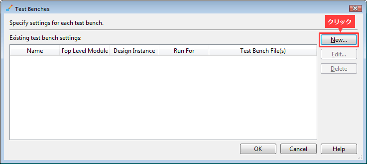
Set the following items in the New Test Benches Settings dialog Box.
・ Test bench name: Enter the module name of the test bench (enter the Top Level module in test bench column at the same time)
・ Simulation period : Set the end time of simulation execution
・ File name : Click the [...] button on the right end and select the testbench file. Register with the Add button.
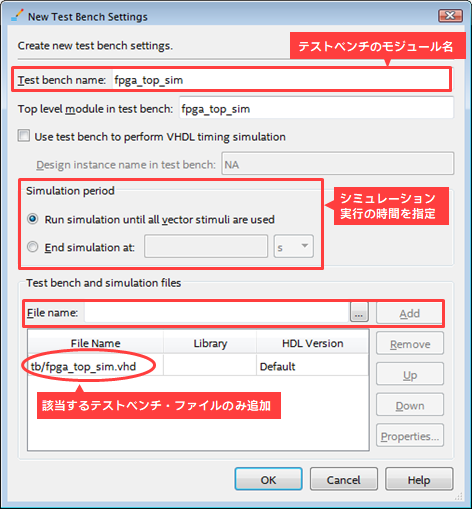
Close each window with OK to return to the Settings window.
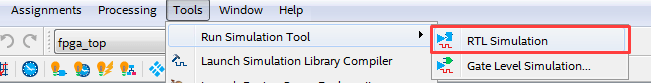
4. Perform function simulation with NativeLink!
Click Tools menu ➤ Run Simulation Tool ➤ RTL Simulation.
* Analysis & Elaboration or Analysis & Synthesis or Fitter process must be executed in advance to execute RTL Simulation.
However, do not run Start Compilation (Processing menu). EDA Netlist Writer automatically runningSisters
Scripts are not generated for successful RTL Simulation.
(If you have run a full compile, run Analysis & Elaboration or Analysis & Synthesis again, or run the Fitter again.
Do RTL Simulation. )
Compile in Questa - AFE, apply library, load, add signals to Wave window, and run simulation. All these operations are performed automatically and the waveform is displayed in the Wave window.
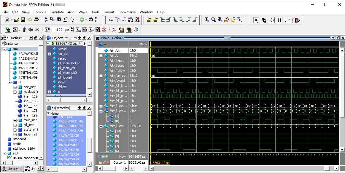
Users only need to check the Wave window! How efficient!
By all means, please try to perform function simulation with NativeLink.
Click here for recommended articles/materials
Monitor the internal signals of Altera® FPGA in simulation <Questa* - Altera® FPGA Edition>
Monitor the internal signals of Altera® FPGA in simulation <Test bench writing>