- Semiconductor BusinessHOME
- Products and Services of Macnica,Inc.
-
technical information

-
Events and Seminars
- Handling Manufacturer
- Support
- Inquiry
- Click here to purchase products
- Semiconductor business e-mail magazine registration
![]()
![]() Narrow down by specifying conditions
Narrow down by specifying conditions
現在2004件がヒットしています。check


hello.
My name is Intel F. Hanako and I provide technical support for Intel® FPGA products at Macnica.
When performing function simulations with ModelSim* - Intel ® FPGA Edition (hereafter ModelSim - IFE), you can of course refer to (monitor) signals at the pin level of the Intel FPGA, but you can also refer to the internal signals of the FPGA at the same time. you want to
The following methods are available to display FPGA internal signals in the Wave window during simulation.
[A] Describe and display in the testbench
[B] ModelSim - Display with GUI operation of IFE
This time, I will introduce [A] How to describe and display in the testbench (that is, how to write a testbench that displays the internal signals of the FPGA in the Wave window).
sample design
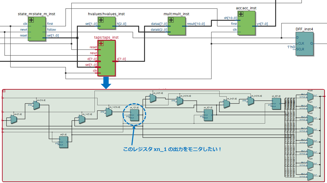
Below is an example design as viewed in the Quartus Prime RTL Viewer.
A submodule of this design is taps (instance name: taps_inst).
This time, we will guide you with an example of referring to the output of the internal register xn_1 (7bit) of taps.
Note that the instance name of the FPGA top-level module in the testbench is fpga.
How to write a testbench
Writing a testbench to monitor the internal signals of your design varies from language to language.
Verilog HDL users, see here.
VHDL users, see here.
Even if Verilog HDL and VHDL are mixed in the lower hierarchy, it can be referenced by this method.
How to write Verilog HDL
In Verilog HDL, there is generally a description method that refers to internal signals of lower-level modules.
Declare a local signal in wire to reference the internal signal, and separate the hierarchical path to the desired signal with a “.” (dot).
Hierarchical paths are specified using instance names.
For example, to refer to the output of register xn_1 in taps:taps_inst, write as follows.
wire [7:0] moni = fpga.taps_inst.xn_1;* moni is the name of the signal to which the internal signal to be referenced is connected, and the name is arbitrary by the user.
How to write VHDL
VHDL does not have an internal referencing syntax like Verilog HDL.
But ModelSim* (including ModelSim* - Intel ® FPGA Edition) can handle it with Signal Spy feature!
In VHDL, add the following util package (modelsim_lib library) to the testbench.
library modelsim_lib; use modelsim_lib.util.all;Then add a local signal to reference the internal signal with a signal declaration and specify it with init_signal_spy using the process statement.
init_signal_spy (src_object, dest_object,verbose);src_object: Hierarchical path of the referenced signal
dest_object: Hierarchical path of the signal name to which the referenced signal is connected
verbose: message output; 1, no output; 0
Hierarchical paths are specified using instance names.
For example, to refer to the output of register xn_1 in taps:taps_inst, write as follows.
* moni is the name of the signal to which the internal signal to be referenced is connected, and the name is arbitrary by the user.
architecture bench of top_tb is ・・・ signal moni : std_logic_vector (7 downto 0); ・・・ begin ・・・ monitor : process begin init_signal_spy("/fpga/taps_inst/xn_1", "/moni", 0); wait; end process monitor; ・・・
This time, I introduced how to write a test bench that monitors the internal signals of the design.
This description will improve the work efficiency of the simulation. Give it a try!
Click here for recommended articles/materials
How to use ModelSim* to monitor Intel FPGA internal signals in simulation
Let NativeLink solve your FPGA function simulation
ModelSim® - Intel® FPGA Edition - How to RTL Simulation