- Semiconductor BusinessHOME
- Products and Services of Macnica,Inc.
-
technical information

-
Events and Seminars
- Handling Manufacturer
- Support
- Inquiry
- Click here to purchase products
- Semiconductor business e-mail magazine registration
![]()
![]() Narrow down by specifying conditions
Narrow down by specifying conditions
現在2172件がヒットしています。check

hello! I'm Ryosu, a new engineer on the Lattice team.
Last time, we created an SPI communication module and checked the actual machine.
This time, we will create a module that displays the acquired temperature data on a 7-segment LED display.
After creating the module, I would like to check the overall operation on the actual machine and complete it!
For those of you who are visiting this blog for the first time, let me give you a brief overview of this blog.
In this blog, I will introduce the process of making a temperature sensor that controls 7 segments with FPGA.
(If you're interested, I'll attach links to other episodes below, so please take a look!)
How to make the LED light up?
We completed SPI communication by the last time. Now it's time to create the final module.
Create a module that displays the temperature data acquired by SPI communication on the 7-segment LED board that was created in the third article.
Since it is just a simple display using dynamic lighting, make it a module that flows data!
yeah? Can the acquired temperature data be displayed as it is? . .
I figured it wouldn't be that simple, so I decided to do some research.
Dynamic lighting and decoding function
Upon examination,
We found that the following two functions are necessary to realize the specifications for displaying on a 7-segment LED.
①Dynamic lighting function
→ For dynamic lighting, switch the digits
It is done at a constant cycle (at a speed that the human eye cannot detect as switching)
This is a method to light up as if multiple digits were lit at the same time.
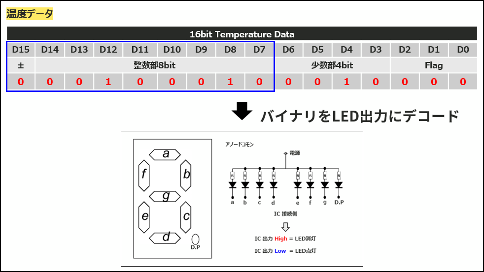
② Decoding function
→ The temperature sensor is temperature data in binary notation.
It is necessary to convert this binary data to the numbers a to g of the 7-segment LED display and each digit.
Using the above two functions, we will create a module that can display binary data in numerical notation.
RTL and Model Sim simulation
Functional examination and RTL description
Create a module that achieves two functions.
The seg_dec. module created this time is a module that realizes dynamic lighting and decoding.
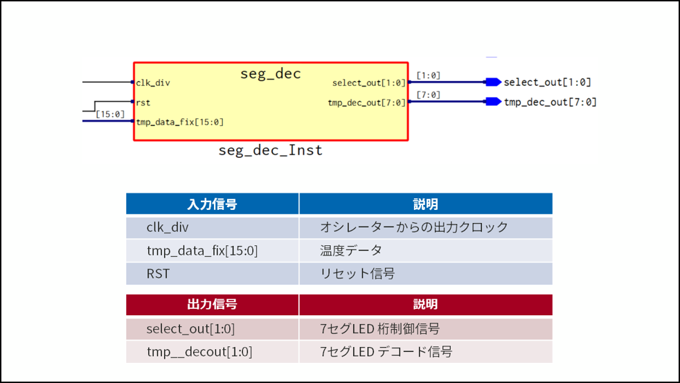
For dynamic lighting, a counter is used to output so that the ones digit and tens digit can be switched.
For the decoding function, 8-bit integer is extracted from the input 16-bit temperature data.
Decode so that 7-segment LED a~g, DP and integer 8bit correspond.
Since we are using common anode LEDs this time, the last output is inverted.
I've posted the source code below, so if you're interested, I'd be happy if you could take a look!
I tried to simulate with Model Sim
Now that the RTL description is complete, let's simulate using Model Sim!
In Diamond, create a testbench and put temperature data as the test environment.
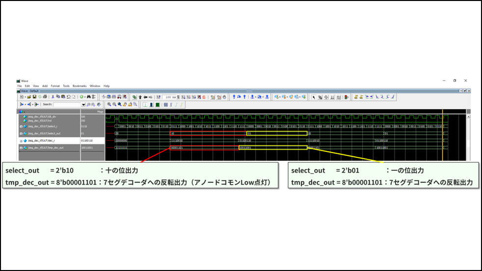
Yes, it looks fine!
Looking at the output waveform, you can see that the digit transition and the output of the 7-segment LED are inverted. (inversion of output from dec_r)
This time, in order to facilitate debugging, the simulation was performed with a small number of counters.
Now, I would like to check the actual machine by connecting it with the SPI module that I made up to last time! (slightly excited)
finally! Connect all the modules and check the actual machine!
Since I created the SPI communication module, the RTL description and simulation have been performed smoothly so far.
Next, I would like to connect all the modules, write the programming data to the FPGA, and check if it works on the actual machine.
The FPGA used in the actual machine uses an evaluation board equipped with Lattice's XO3LF-6900C-5BG256C.
It is a user-friendly device with 3.3v single drive and built-in Flash!
If you are interested, please check the features of XO3LF below!
Overall module display, complete!
Now that the RTL design and simulation have been confirmed, it's time to check the actual machine.
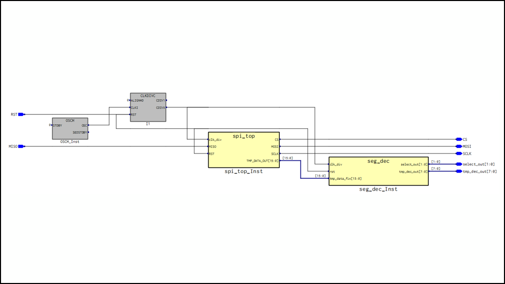
Connect the SPI communication module and the seg_dec module in the TOP module,
Add CLKDIV (division module) and OSCH (internal oscillator).
When Synplify Pro is launched by itself and the RTL is visualized, it looks like this
On Diamond, pass the Process up to Translate Design and compile without errors, then perform pin placement.
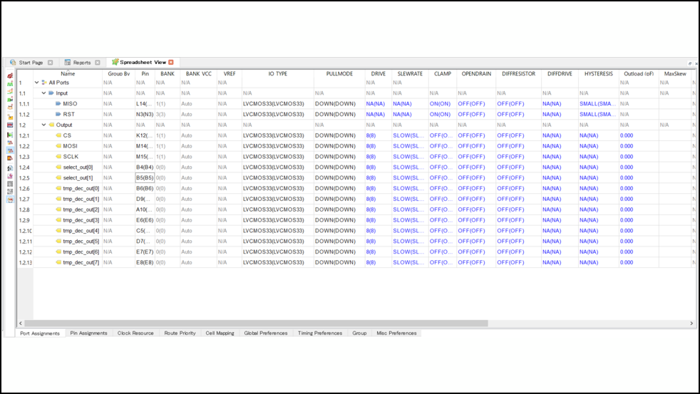
Set on Diamond SpreadSheetView.
Set the pin assignment, IO Type, and PULLMODE in the Port Assignments tab.
Set IO Type to LVCMOS33 and PULLMODE to PULLDOWN. This is set by looking at the specifications of the target device.
After pin placement is completed, the process is passed to Export Files to generate programming data files to be written to FPGA.
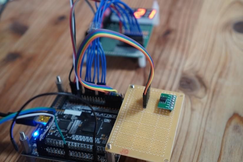
Write programming data file to FPGA,
Connect the temperature sensor, FPGA evaluation board, and 7-segment LED board as shown in the picture below.
Put a battery in the 7-segment LED board and turn on the power to the FPGA evaluation board.
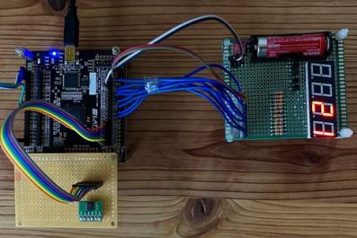
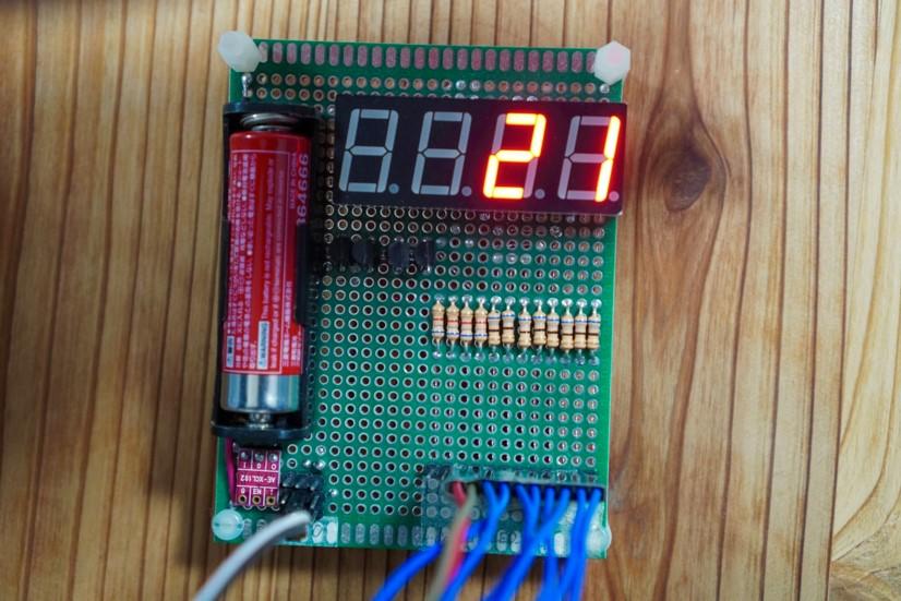
You can see that such a number is displayed on the 7 segment LED!
Since the temperature was almost the same as the room temperature, it seems that the temperature data was successfully decoded into the 7-segment LED.
It's more plain than I thought, but I'm very happy that it's all finished! !
I regret that I should have added a few more functions (laughs)
This time, we will create a circuit to display on the 7-segment LED display,
It was completed in combination with the SPI communication module created so far.
As an impression,
I'm so happy that we made it from scratch to finish!
I made a lot of failures, but I was able to grow as much as I failed.
This is the final episode of Ryosu no Hosomichi SPI Communication Module.
Thank you to everyone who has continued to visit us!
Also, I would like to update if there is an opportunity to decide the theme and produce it. See ya!
About the Lattice FPGA Getting Started Blog
Throughout the article, we are making a module that converts the temperature (SPI communication) acquired by the temperature sensor inside the FPGA and displays it on the 7-segment LED display!
If you are interested in "What is this newcomer making?"
I would be happy if you could check the module production process and the whole picture from the page below!
About Diamond Archive Seminar
Lattice design tool Diamond will be an archive seminar where you can learn for free.
In this archive seminar, we will introduce the basic usage of Lattice Diamond.
Since it is divided into the following items, it is possible to watch only the part that interests you.
-------------------------------------------
[Diamond Archive Seminar]
1.First of all
2. Create a project
3. RTL and IP generation
4. Logical simulation
5. Place and Route and Timing Constraint/Analysis
6. Programming
7. Internal Node Observation
-------------------------------------------
We would appreciate it if you could check it out from the page below!
Related information