- Semiconductor BusinessHOME
- Products and Services of Macnica,Inc.
-
technical information

-
Events and Seminars
- Handling Manufacturer
- Support
- Inquiry
- Click here to purchase products
- Semiconductor business e-mail magazine registration
![]()
![]() Narrow down by specifying conditions
Narrow down by specifying conditions
現在2189件がヒットしています。check

hello! I'm Ryosu, a new engineer on the Lattice team.
This time, I would like to check the operation of the 7-segment LED board.
Last time, I introduced how to obtain a license, install design tools, and evaluate the XO3LF evaluation board.
For those of you who are visiting this blog for the first time, let me give you a brief overview of this blog.
In this blog, I will introduce the process of making a temperature sensor that controls 7 segments with FPGA.
(If you're interested, I'll attach links to other episodes below, so please take a look!)
7 segment LED
This time, I would like to check the operation of the 7-segment LED.
If I remember correctly, I feel that there was a direction in which current flows through an LED, which is called something like a XX node.
So, I tried to find out how the LED lights up.
anode? Cathode?
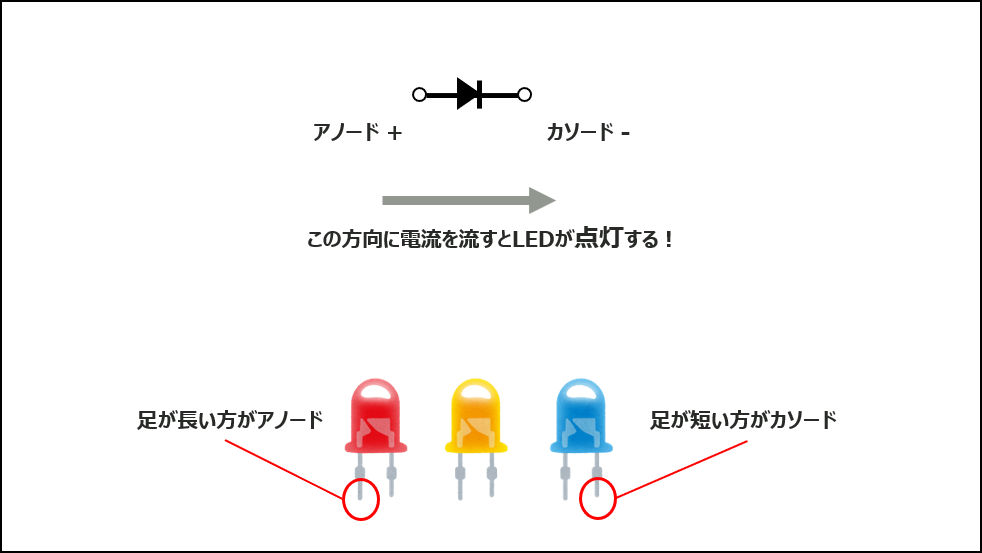
LEDs have polarities called anode and cathode.
In order for an LED to glow, current must flow in the correct anode/cathode direction.
As shown in the figure below, the anode is plus (+) and the cathode is minus (-).
To make an LED light up, current flows from the positive side to the negative side.
If you check the data sheet, it says in which direction the current should flow, so be sure to check it.
Also, in the case of such a bullet-shaped LED, the longer leg is the anode, and the shorter leg is the cathode.
This time, I'm using an LED display instead of a cannonball-shaped LED, so maybe the lighting is different? I decided to do a little more research.
Anode common and LED indicator
I understand the basic concept of LED.
However, I wanted to make the LED display light up this time, so when I looked it up, I found the words anode common/cathode common.
common?
After looking into it, it seems that common means common, and LED indicators are used to save the number of I/Os.
It turns out that the anode/cathode of many LEDs are common.
The 7-segment LED display used this time is an anode common LED.
Anode common is an LED that uses a common anode as shown in the figure below.
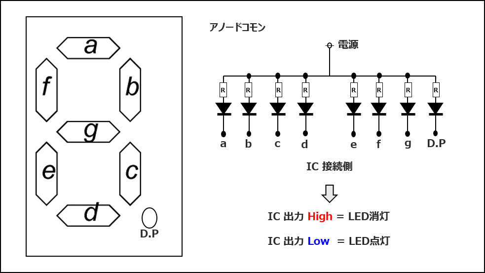
Anode common is illuminated by sinking current.
To sink current, connect the external power supply to the anode side and the IC's output port to the cathode.
By dropping the output port of the IC to Low, current flows through the LED and it becomes a mechanism that lights up.
In addition, the 7-segment LED display
As shown in the figure above, 7 LEDs a~g and the decimal point (DP) are turned on/off to represent numbers.
Checking the operation of the 7-segment LED display
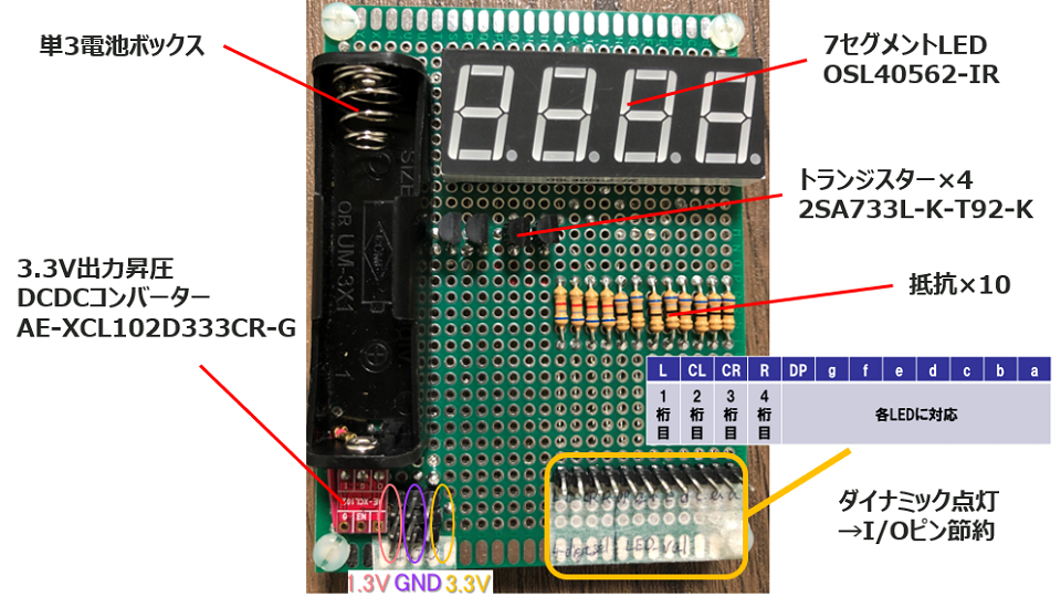
Now that you understand the principle of lighting and how to make it shine, make a 7-segment LED board based on the configuration diagram. (1st publication)
It looks a little cramped because it was designed as compact as possible, but the 7-segment LED is placed on the upper right and the battery Box is placed on the upper left.
Pins are placed on the bottom right so that it can be connected to the XO3LF evaluation board with a cable, and power and GND are placed on the bottom left.
Before making this board, my senior said,
"If you draw a lot of wires to display 2 digits, the number of I/O on the FPGA side will be insufficient."
They said.
At the same time, "It's better to use dynamic lighting."
I was also taught.
Dynamic lighting is a way to switch the digits displayed on the FPGA side to save I/O pins.
To explain in a little more detail, dynamic lighting is performed by switching between digits.
This is done at a constant cycle (at a speed at which the human eye cannot detect switching).
This is a method to light up as if multiple digits were lit at the same time.
I would like to control the digits by this dynamic lighting with FPGA as well as LED control.
I created a circuit diagram using free software!
The schematic is shown below.
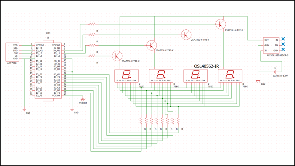
A little left of the center is the FPGA bank.
The left side of the bank is the temperature sensor, and the right side is the 7-segment LED circuit.
The point of the 7-segment LED circuit is to control the digits of the 7-segment LED display with four signal lines in order to reduce the number of IOs used.
I would like to display two digits using dynamic lighting.
Here is the actual board I made.
I used a soldering iron for the first time in a long time, and it took a considerable amount of time to make one board.
After the board has been manufactured, a power check is performed with a tester.
After confirming that there is no short circuit, check the operation to see if the 7-segment LED actually lights up.
It's exciting to see if it lights up well
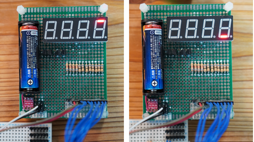
It will be a very plain work, but we will check whether it lights up properly one by one.
All lit up! Was good!
I was able to confirm that all four digits light up safely, so I'm done checking the operation of the 7 LEDs.
This time, we checked the operation of the 7-segment LED.
As an impression,
I was impressed that the LED display that I soldered and connected properly lit up! (crying)
Next time, I would like to talk about checking the operation of the temperature sensor.
See you next time! See ya!

About the Lattice FPGA Getting Started Blog
This article focuses on LED control. But not just LED control
Throughout the article, we are making a module that converts the temperature acquired by the temperature sensor inside the FPGA and displays it on the 7-segment LED display!
If you are interested in "What is this newcomer making?"
I would be happy if you could check the module production process and the whole picture from the page below!