- Semiconductor BusinessHOME
- Products and Services of Macnica,Inc.
-
technical information

-
Events and Seminars
- Handling Manufacturer
- Support
- Inquiry
- Click here to purchase products
- Semiconductor business e-mail magazine registration
![]()
![]() Narrow down by specifying conditions
Narrow down by specifying conditions
現在2172件がヒットしています。check

hello! I'm Ryosu, a new engineer on the Lattice team.
This time, I would like to check the operation of the selected temperature sensor.
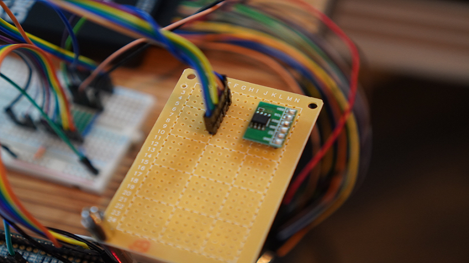
To check the operation, we will check the operation of the temperature sensor using Digilent's Analog Discovery and an oscilloscope.
Last time, we checked the operation of the 7-segment LED board,
I studied how to control the LED with anode, cathode and FPGA.
For those of you who are visiting this blog for the first time, let me give you a brief overview of this blog.
In this blog, I will introduce the process of making a temperature sensor that controls 7 segments with FPGA.
(If you're interested, I've attached links to other episodes below, so please take a look!)
How to check the operation of SPI communication?
I will check the operation of the temperature sensor immediately.
However, I don't know how to check if it works.
Do I have to start from the point of making SPI communication?
I consulted with seniors.
Ryosu "Mr. F, I'm thinking of checking the operation of the temperature sensor, but I'm thinking of making it from SPI communication."
Senior F-san: "I think it's fine, but how do you check if the communication you created is correct?"
Ryosu 「、、、、、、」
Senior F-san "You should use a debugger called AnalogDiscovery!"
"Evaluation can be done easily by operating the GUI without having to bother to create communication!"
Ryosu "I will use it!"
So, if I bothered to create SPI communication for evaluation, it would take a tremendous amount of time.
It seems that it will take time to check whether the created program is correct,
I decided to evaluate the sensor with AnalogDiscovery.
Check the specifications of the SPI temperature sensor ADT7310
About the temperature sensor used this time
Before checking the operation of the temperature sensor,
What kind of data is output from the temperature sensor?
Is there anything to do from the FPGA side?
You'll need to look at the datasheet to confirm usage.
The temperature sensor of choice is the Analog Devices temperature sensor module ADT7310.
This temperature sensor operates at 3.3V and outputs measured temperature data to the SPI bus, with a range of -55°C to 150°C.
SPI temperature sensor communication method
I had a hard time reading the English manual.
I checked the sensor specs and found the following:
・It is necessary to write/read by SPI communication
・In terms of my concept, Write should be the default setting when the power is turned on.
・Temperature data is output when reading is performed by SPI communication.
・Temperature data is output as 13bit data + flag
The table below summarizes
Send a command and talk to the sensor!
This sensor gets temperature data through SPI communication.
Write/Read to the register is
The Write command configures the registers,
The Read command accesses the registers and retrieves the temperature data.
Write? do not do?
Temperature data is stored in the register as 13bit data.
This 13bit temperature data will be the default resolution.
By sending a Write command
You can change the resolution to 10bit, 16bit, etc.
Considering the "displaying the room temperature as an integer" this time
I just need to know roughly the current room temperature
I decided to use the default resolution without changing it.
Therefore, this time, I decided not to send the write command (the default setting after turning on the power).
What should I send for the Read command?
Access the register and get 13bit temperature data
In what order is the 13-bit temperature data output from the temperature sensor?
If you check the datasheet of the ADT7310
Apparently, the error flag is output as a total of 16-bit data along with the 13-bit temperature.
There are also several methods of outputting temperature data.
ONE-SHOT MODE to output temperature once,
For example, 1SPS MODE that outputs temperature at 60ms cycle.
This time we will not use any special mode and will use the default CONTINUOUS READ MODE.
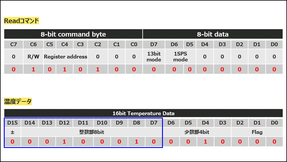
In this mode, once you write the command (0x54) to the register, you only need to send 16 bits of 0 thereafter.
It becomes a mode in which temperature data is returned.
Therefore, when reading, send 0x54 to the temperature sensor and send dummy data 0 for 16 bits.
Try Digilent's Analog Discovery! However,,,
For Write, the default setting after turning on the power is fine.
Temperature data can be obtained by sending a Read command to the temperature sensor.
Now that I know, I would like to check if the temperature can be obtained using Analog Discovery.
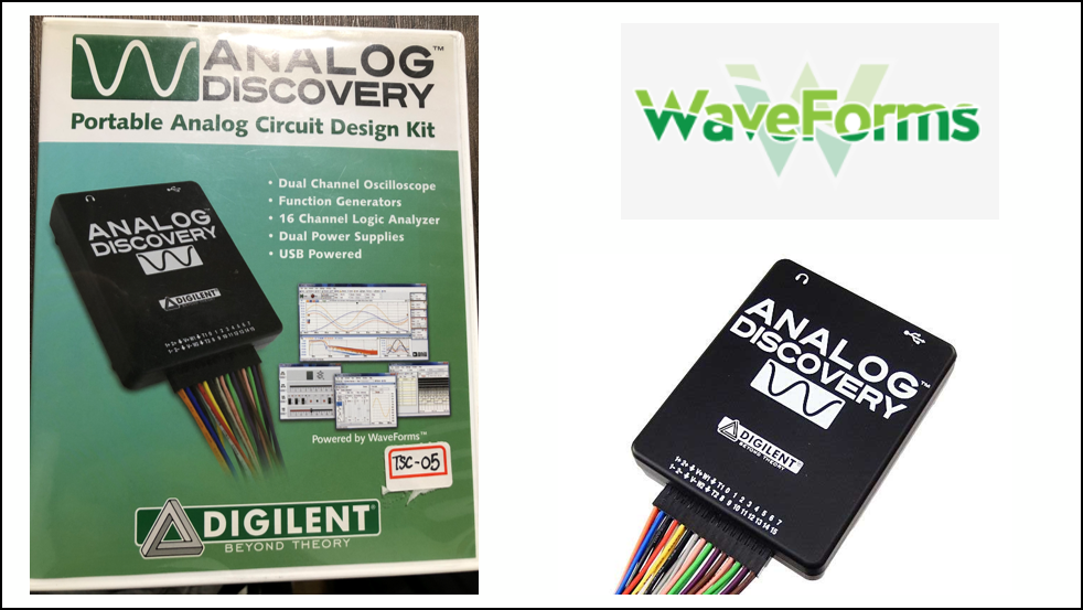
AnalogDiscovery is a pocket-sized all-purpose instrument with functions such as Digilent 's oscilloscope and function generator.
Install and use this device and WaveForms, which is free to install.
This time, we will send arbitrary commands to the temperature sensor using the function "Protocol" that can easily send Write/Read commands with the device.
I would like to check whether the temperature value equivalent to the room temperature of the verification environment is returned.
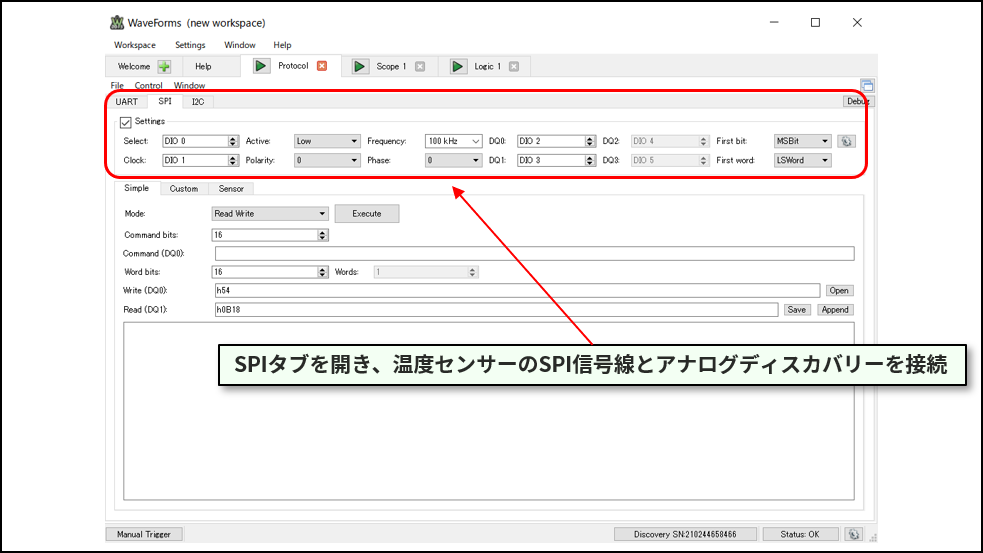
First, connect the Analog Discovery and the temperature sensor and launch the downloaded WaveForms.
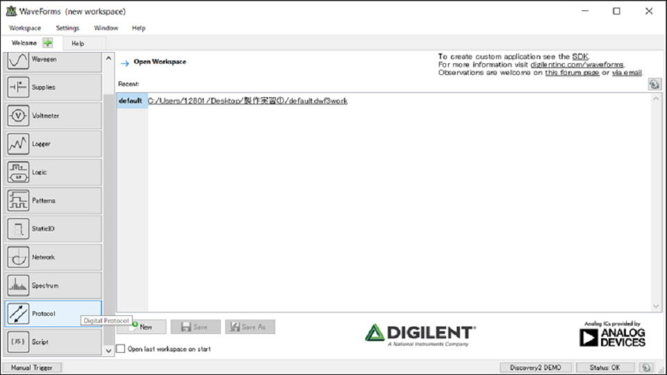
Next, select Protocol and make various settings.
Connect the signal lines DIO0/1/2/3 from AnalogDiscovery to Select (Chip Select), Clock (SCLK), DQ0 (MOSI), and DQ1 (MISO) respectively.
Next, configure various settings such as mode settings and commands to set the default mode of the sensor.
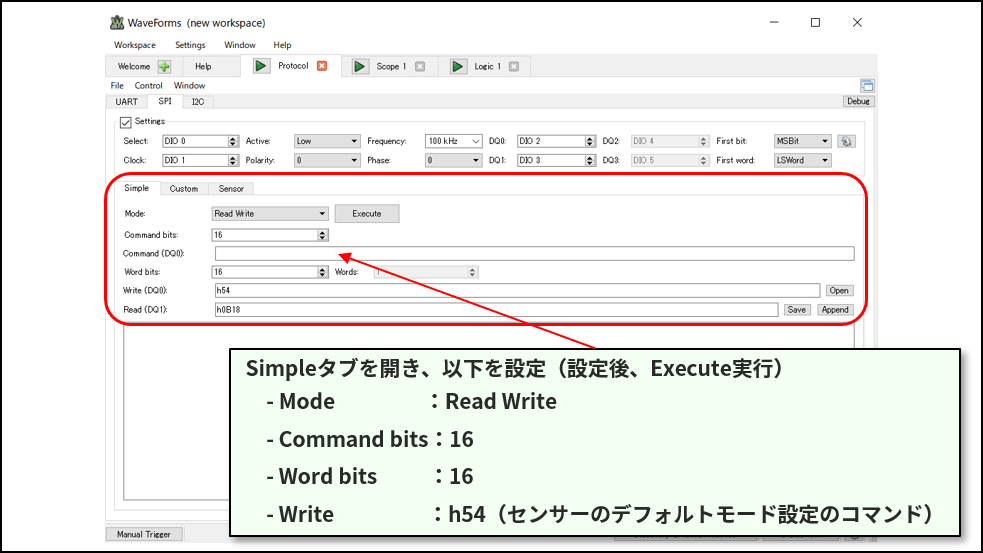
Since the connection and various settings have been completed, press the Execute button to execute.
It would be nice if I could get something like temperature in one shot, but my heart is pounding
When you execute the Execute button, the results of Write and Read are output in the lower left.
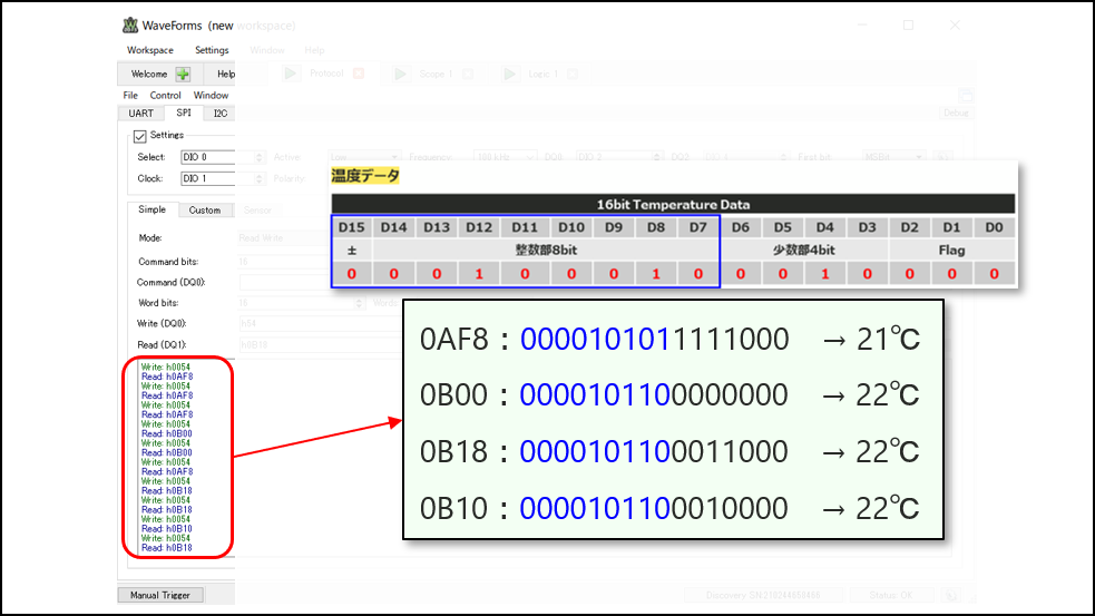
Along the way to read the output data from the temperature sensor that you understood earlier
Reading the temperature data...
There is an error below the decimal point,
We were able to confirm that this value is close to the room temperature of 21.5°C at the time of observation! !
Therefore, I know that the temperature data is output normally from the temperature sensor, so I would like to finish the operation check.
As an impression,
At first, I didn't really understand how to use AnalogDiscovery, and as a result of trial and error, I was able to check the temperature data from the temperature sensor.
The excitement when I was able to confirm the operation was amazing! !
Next time, I'd like to move on to RTL design.
See you next time! See ya!

About the Lattice FPGA Getting Started Blog
This article focuses on LED control. But not just LED control
Throughout the article, we are making a module that converts the temperature acquired by the temperature sensor inside the FPGA and displays it on the 7-segment LED display!
If you are interested in "What is this newcomer making?"
I would be happy if you could check the module production process and the whole picture from the page below!
Related information