- Semiconductor BusinessHOME
- Products and Services of Macnica,Inc.
-
technical information

-
Events and Seminars
- Handling Manufacturer
- Support
- Inquiry
- Click here to purchase products
- Semiconductor business e-mail magazine registration
![]()
![]() Narrow down by specifying conditions
Narrow down by specifying conditions
現在2183件がヒットしています。check

Pros and cons of ground pattern between wiring
It is common practice to insert a ground pattern between board patterns.
Since it has a shielding effect, you probably think that crosstalk can be suppressed for some reason.
I think that this "for some reason" should be stopped.
For example, it has been theoretically proven that increasing the distance between the patterns of the coupled lines certainly reduces the crosstalk.
However, a trace grounded at both ends has mismatched impedances at both the near and far ends.
In general, only one point of impedance mismatch in a distributed parameter line is acceptable.
For example, in general signal transmission, using a damping resistor is considered to reduce the degree of near-end impedance mismatch to an acceptable level.
The output resistance of a 12mA driver is about 22Ω. Assuming that the characteristic impedance Z0 of the line is 50Ω, a damping resistor of about 11Ω is inserted to make the output resistance 33Ω.
At this time, the near-end reflection coefficient is (33-50)/(33+50)=-0.2, and the degree of mismatch is considered to be within the allowable range.
In contrast, a trace grounded at both ends has two mismatches.
This time, we will consider this ground pattern.
As a circuit, we solve the equations for three coupled lines.
A 4096-point FFT is used in the same way as the differential crosstalk with four coupled lines.
For details, please see my book (references).
In the following analysis, the output resistance of the driver is 33Ω (equivalent to an 8mA driver), the signal amplitude is normalized to 1V, the rise time is 0.5ns (0-100%), and the wiring length is 10cm unless otherwise specified. The repetition period T and pulse width are T=100ns and TW=30ns.
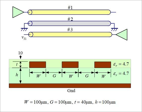
As shown in Figure 1, consider a ground line (#2) between the perpetrator line (#1 below) and the victim line (#3). A ground line connects both ends to ground.
The pattern width is 100um for all lines, and the line gap G is also 100um.
First, consider near-end crosstalk, where signals #1 and #3 have opposite directions. i.e. parse the v31 waveform.
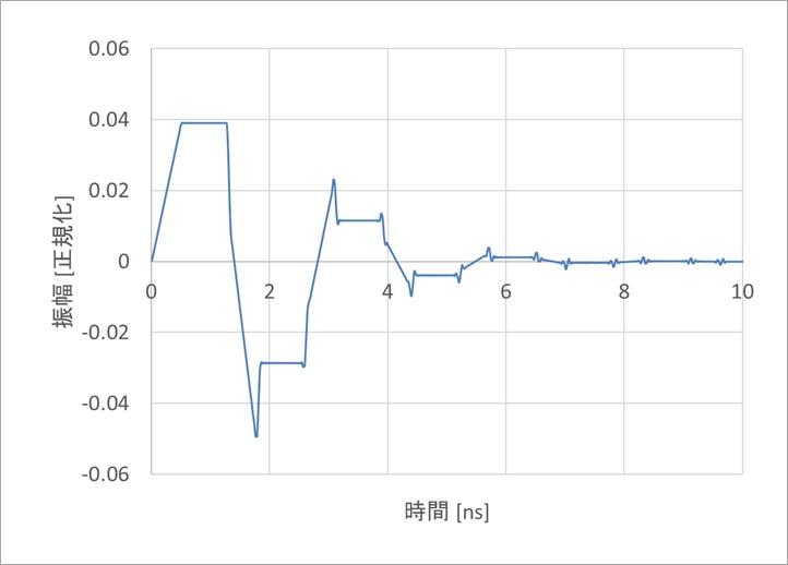
Figure 2 is an analysis example when #2 does not exist, that is, when the line gap is 2G+W=300um (crosstalk coefficient ξ is 0.06).
The first rise in noise is 0.04V, or 4% crosstalk.
A crosstalk of 4% is almost a satisfactory value (honor student), but since the line gap is as wide as 300um, I think that crosstalk can be somewhat reduced by passing another pattern here and grounding it. may be normal.
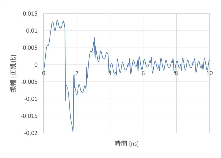
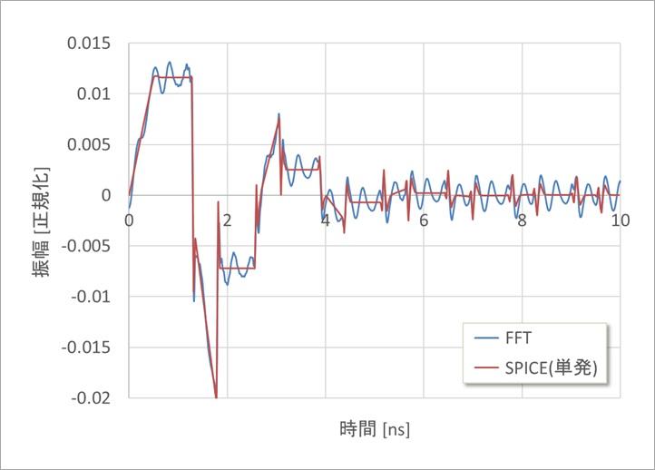
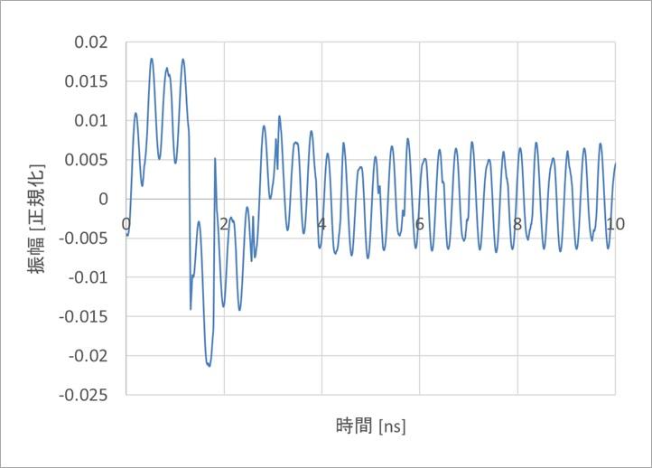
Figure 3(a) is an analysis example when both ends of #2 are grounded according to the idea of "somehow".
The rising portion is 0.01 V, and crosstalk is certainly smaller than in Figure 2, but high-frequency noise is superimposed on the noise.
Figure 3(b) shows the analysis results for a single SPICE case overlaid on the repetitive waveform of Figure 3(a).
As the high frequency noise continues, it overlaps the noise of the previous period.
Figure 3(c) is an analysis example when T=20ns and TW=10ns. The high frequency components overlap (resonate) and increase. Even a slight change in the period T can significantly change the state of resonance.
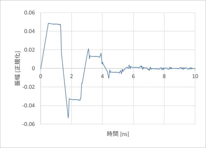
Figure 4 shows the case where both ends of #2 are open. The rising part is 0.05V, which is slightly larger than in Fig.2. No high frequency resonance is observed.
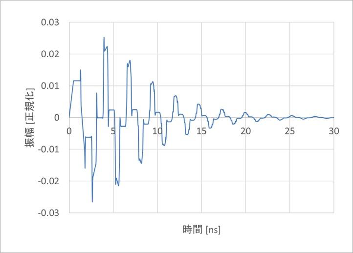
Figure 5 shows #2 with the near end connected to ground and the far end open.
The rising part is 0.01V, but the crosstalk does not converge.
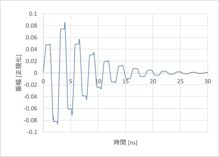
Figure 6 shows 0.05V when the near end of #2 is open and the far end is grounded, contrary to Figure 5.
By now we know that it doesn't make sense to open at least one side of #2.
So, consider the case where both ends of #2 are grounded.
Influence of line length
Figures 2 to 6 all have a line length of 10 cm, but we analyzed 5 cm and 20 cm.
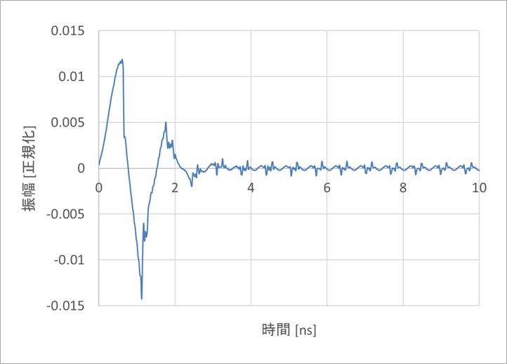
Figure 7 is an example of 5 cm. The frequency of high frequency noise is increasing and the amplitude of high frequency noise is decreasing.
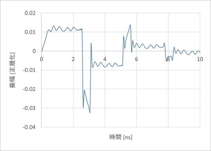
Figure 8 is an example of 20cm. The high frequency components have a lower frequency and a larger amplitude.
#2 has a reflection coefficient of -1 because both ends are grounded.
Since opposite-phase reflection occurs at both ends, for example, a rising waveform starting from the near end is reverse-phase-reflected at the far end, becomes a falling waveform, and returns to the near end. It can be imagined that at the near end, the opposite phase reflection occurs again, forming a rising waveform, and heading toward the far end, in other words, the opposite phase reflection is repeated forever.
Considering Figures 7 and 8 together with Figure 3, this high frequency component is dependent on the line length.
Now consider the signal at the midpoint of #2.
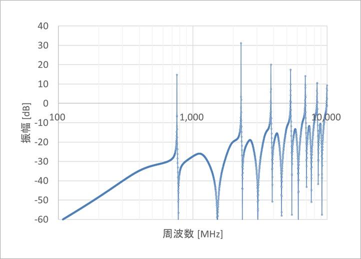
Figure 9 shows the transfer function from the near end of #1 to the midpoint of #2.
There is a sharp peak between 700MHz and 800MHz.
In the same figure, the sharp peaks cannot be reproduced accurately because the two digits (100MHz to 10GHz) are calculated at 3,000 points.
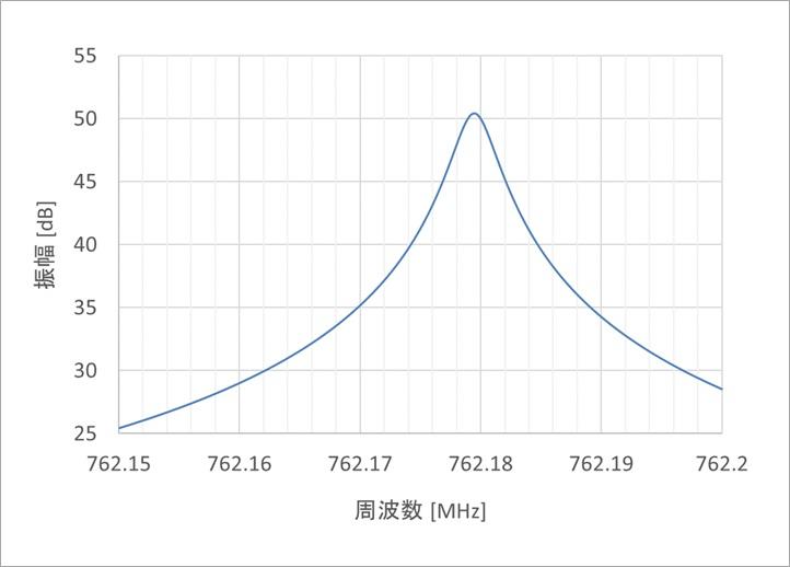
In Fig. 10, when the frequency resolution was increased and the peak was found, it was 762.18MHz, and the gain was about 50dB (approximately 300 times).
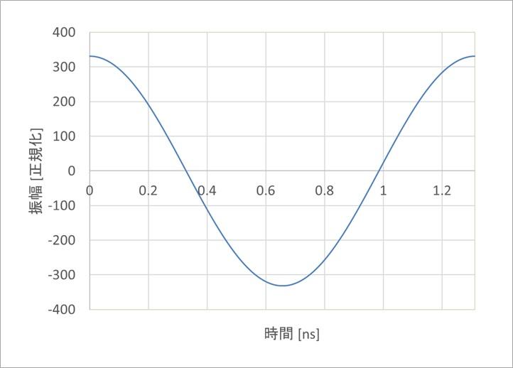
Figure 11 shows the waveform at the midpoint of #2 when the driver signal is a sine wave (sin) with an amplitude of ±1.
A cosine wave (cos) of ±300 for a driver amplitude of 1.
Since the driver's pulse waveform has a wide range of frequency components, a component 300 times greater than the specific component appears at the midpoint of #2.
This makes #2 behave like a long suspension bridge or an open guitar string. Even if both ends are fixed, the middle point will vibrate.
In other words, reflection is repeated at both ends of #2, and resonance is generated.
It is easy to guess that this particular frequency component is emitted from #2.
Notice the number 50dB.
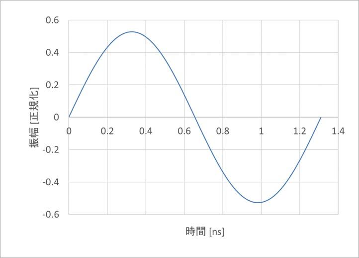
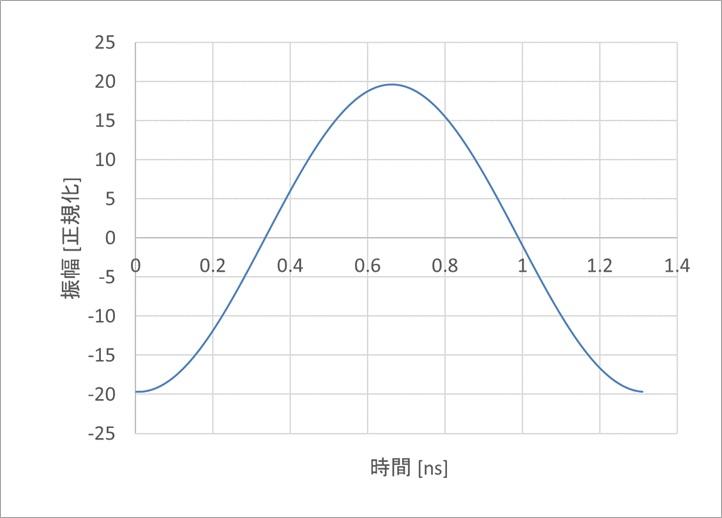
Figure 12 is the near end voltage of #1 at this time, and Figure 13 is the far end voltage of the same. The component of this frequency is transmitted 20 times. Think of this as a resonance between #2.
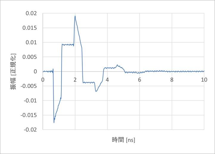
Figure 14 is an example of far-end crosstalk, where the #1 and #3 signals are in the same direction.
There is some resonance, but not as much as the near-end crosstalk.
A similar analysis was performed for the intermediate layer (strip line).
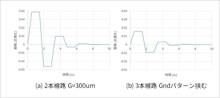
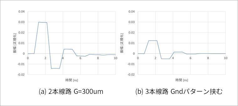
Figure 15 is an analysis example of near-end crosstalk in the intermediate layer, and Figure 16 is an analysis example of far-end crosstalk. In either case, the crosstalk amplitude is halved when the Gnd pattern is inserted between the lines when the line gap is G=300um.
High-frequency resonances, such as those occurring in the surface layer, are also absent.
Summary
Sandwiching a ground pattern can slightly reduce crosstalk noise compared to the case without a ground pattern, but resonance of the ground pattern occurs.
For this resonance, one could, for example, put vias to ground at multiple midpoints of #2 to drive the resonance point out of band.
However, considering the diameter and clearance of the vias, the distance between #1 and #3 will be quite large, so even if #2 is not provided, the crosstalk will be sufficiently small that it is practically useless.
As in this case, when there are patterns that connect both ends to the ground in addition to the ground pattern between patterns, it is necessary to be aware of resonance and think about connecting to the ground with many vias.
References
Yuzo Usui: All About Distributed Constant Circuits for Board Designers (3rd Edition) Self-published, 2016
CRPaul: Analysis of Multiconductor Transmission Lines, 2E, Wiley-IEEE Press, 2007
CRPaul : Introduction to Electromagnetic Compatibility, Wiley(2006)
What is Yuzo Usui's Specialist Column?
It is a series of columns that start from the basics, include themes that you can't hear anymore, themes for beginners, and also a slightly advanced level, all will be described in as easy-to-understand terms as possible.
Maybe there are other themes that interest you!