- 半導体事業HOME
- マクニカの製品・サービス
-
技術情報

-
イベント・セミナー
- 取扱メーカー
- サポート
- お問い合わせ
- 製品購入はこちら
- 半導体事業のメルマガ登録
![]()
![]() 条件を指定して絞り込む
条件を指定して絞り込む
現在2171件がヒットしています。check

こんにちは。新人FAEのトンパです。
私は新卒でマクニカに入社し、製作実習でモノづくりを体験しながら回路設計や実装について学んできました。学生時代は有機化学を専攻しており、電気電子の知識が全くない状態からのスタートだったので、度々苦労しました。
そこで本記事では、私が製作実習でモノづくりを体験しながら回路設計や実装について学んだことを紹介しています。前回は、DC/DCコンバーターの実装について紹介しましたが、今回は、DC/DCコンバーターの評価について紹介します。
オシロスコープ
DC/DCコンバーターの評価について紹介する前に、オシロスコープについて簡単に紹介します。

図1:オシロスコープ
オシロスコープとは、電気信号の時間変化を波形として検出することができる装置であり、電源評価時には必須アイテムです。そんな評価時に必要なオシロスコープですが、使用することによって色々な測定をすることが可能です。
■電源評価における主な使用目的:
・出力電圧の大きさの測定
・出力電圧のノイズの測定
・周波数/周期の測定
・出力電圧の立上がり波形の測定
・過渡応答特性の測定
上記のようにたくさんの評価ができますが、本記事では実際に私がおこなった測定について紹介します。
出力電圧の確認
まず初めにおこなったのは、狙った電圧が出力できているかの確認です。
私は、DC/DCコンバータ―のフィードバック抵抗を3種類実装し、スイッチによって3種類の電圧を出力できるように設計をしましたが、無事に出力できているのでしょうか。。。
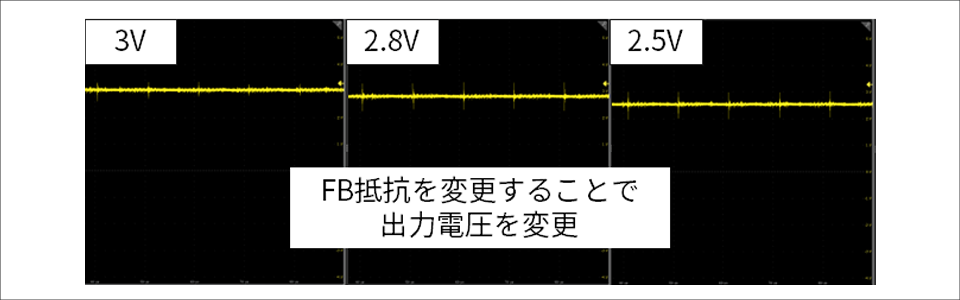
見事狙い通りの電圧が出力されていることが確認できました!この波形を確認できた時は、実習中で一番嬉しい瞬間だったかもしれません。
続いてノイズの確認に移ったのですが、当初は上手くリップル波形を確認することができませんでした。その理由は、ノイズ測定時にもDC測定をおこなっており、波形を上手く拡大できていなかったからです。ノイズ評価の際には、もっと細かく波形を見る必要があり、そのためにはAC設定で測定する方が適していることを教えてもらいました。AC設定にすることで、波形の中心が水平の0V軸に対してどのように変動しているかを正確に観察することができるため、ノイズ評価に適しています。
実際に測定した結果を図3に示します。
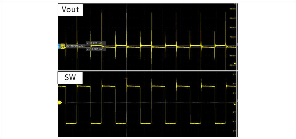
上の波形が出力電圧の波形、下の波形はスイッチング波形を示しており、出力電圧波形では、リップル電圧と鋭く大きいスパイクノイズが確認されました。このスパイクノイズは、主にスイッチの開閉に伴い発生すると言われています。
本当にスイッチングに伴うノイズなのかを確認するために、スイッチング波形と合わせて観測したところ、スイッチがOn/Offするタイミングでノイズが発生していることが確認できました。私の場合、今回のノイズは後段のICの許容範囲内でしたので問題ありませんでしたが、高周波のスパイクノイズを削減するためには、LCフィルターやフェライトビーズを負荷の位置に追加するなどの対策があります。
今回の測定をすることで、AC設定にするなど、用途に合った設定が必要であること、複数の波形を同時に確認することで、よりデバイスの動きが理解できることを学びました。
負荷電流の確認
オシロスコープでは、電圧の波形のみではなく、電流の波形も確認することができます。
「第2回 DC/DCコンバーターの選定」の記事で紹介したのですが、私はモーターの負荷を見誤ってDC/DCコンバーターを選定し、モーターが思ったように駆動しませんでした。その原因を突き止めたのもオシロスコープのおかげなんです。
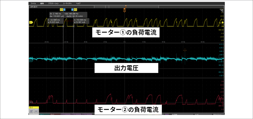
当初は600mAほどの負荷であると想定していましたが、実際に測定すると1A以上の電流を引いていることに気づきました。また、電流波形の立上がりがまばらなのは、電源からの電力供給が足りていなかったためだと考えられます。
この経験から、オシロスコープを使用することで不具合時の解析も可能であることを学びました。
まとめ
今回は、オシロスコープを用いたDC/DCコンバーターの評価について紹介しました。実際に評価をすることで、デバイスがどのように動いているのか、評価時にはその用途に合った設定方法が必要であることなどを学べました。また、オシロスコープを使用し、動作不具合の原因を見つける経験もできました。
ついに次回は、最終回です。お楽しみに。
人生初の回路設計までの道のり 記事一覧
・DC/DCコンバーターの評価
・おまけ編