- Semiconductor BusinessHOME
- Products and Services of Macnica,Inc.
-
technical information

-
Events and Seminars
- Handling Manufacturer
- Support
- Inquiry
- Click here to purchase products
- Semiconductor business e-mail magazine registration
![]()
![]() Narrow down by specifying conditions
Narrow down by specifying conditions
現在2168件がヒットしています。check

Hello, I'm Tompa, a new FAE.
I joined Macnica as a new graduate and learned about circuit design and implementation while experiencing manufacturing in a production training program. I majored in organic chemistry as a student, so I started with absolutely no knowledge of electrical engineering, and I often struggled.
In this article, I will introduce what I learned about circuit design and implementation while experiencing manufacturing during my production training.
And finally, this is the last article. In the previous article (Evaluation of DC/DC Converters), we introduced things related to DC/DC converters, but this time we will introduce some other things we worked on during the practical training. Please enjoy watching and see what we did.
Introduction of the creation
In the first to fifth articles, I introduced what I learned about circuit design through the production training, but I was not able to introduce in detail what I made. Although it is late, what I made was a line trace car. A line trace car is an autonomous vehicle that runs along a line drawn on the ground, and this time I made a car that runs autonomously on a course with black lines drawn on a white board.
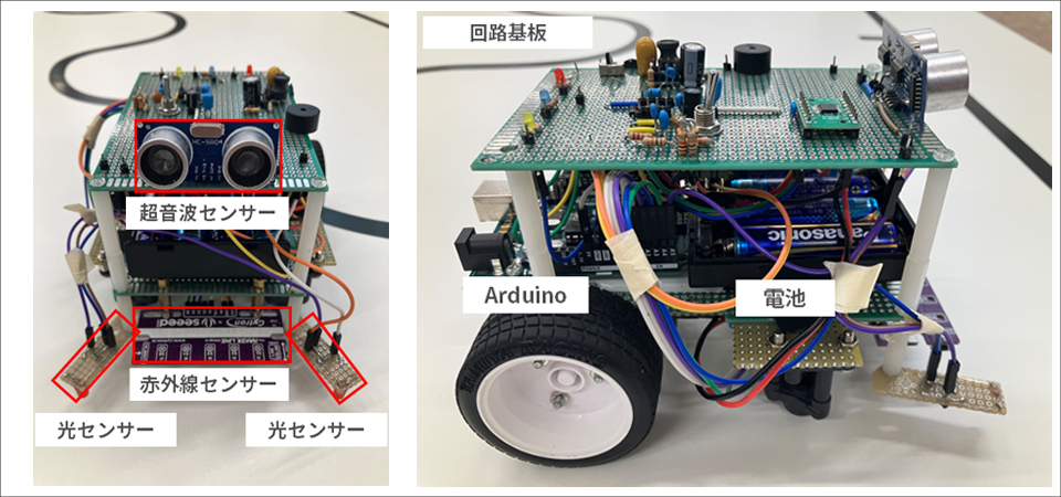
This is the line tracing car we actually made. We used infrared and optical sensors to read the black lines, which is the key to the car. We also used ultrasonic sensors to detect obstacles placed along the course.
The car is made up of two layers, with the microcontroller (Arduino) and battery on the first layer, and the circuit board that I have introduced so far on the second layer. As for the car body, I didn't think too much about wiring between the sensors and the microcontroller, so the wiring became too crowded and awkward as you can see in the picture, which is something I regret.
programming
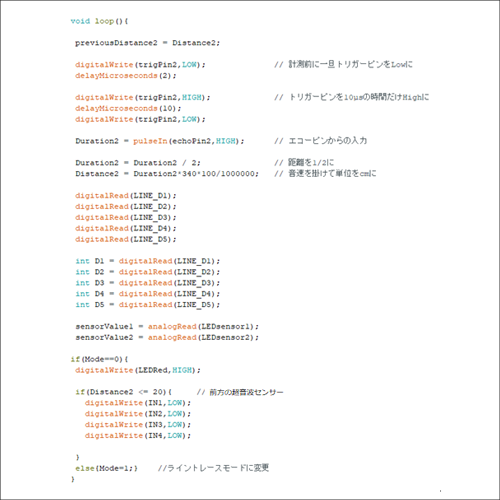
To make a line tracing car, not only is it necessary to make a circuit board, but programming is also required. In the case of a line tracing car, it is necessary to control the running of the car with a microcomputer based on the signals sensed by each sensor. Having never touched programming before, I had no idea what to do or how to proceed, but I was told that I should first create a flowchart.
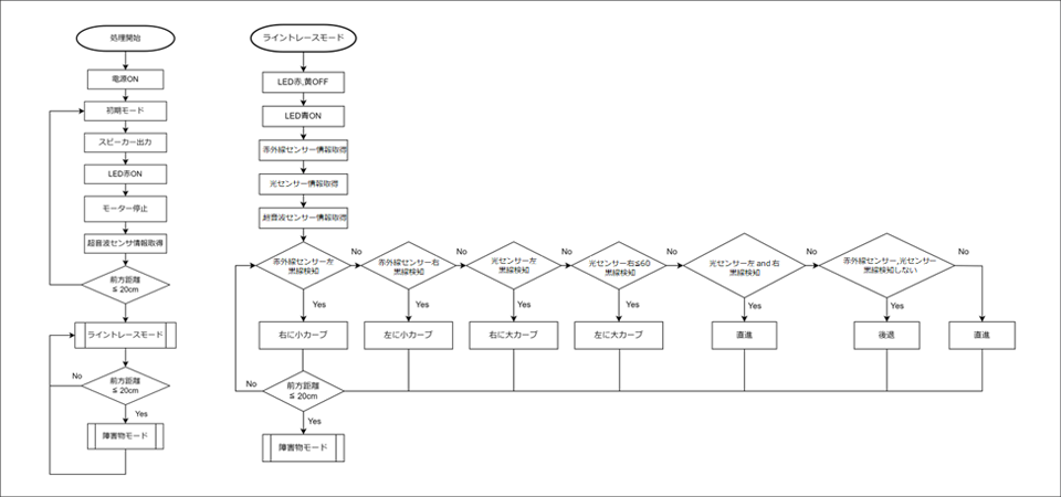
A flowchart is a diagram of a program's instructions, as shown in Figure 2. Creating a flowchart has the advantage of helping you understand the flow of programming processes and making programming smoother.
For me, who has no real programming experience, the flowchart was like a guidepost.
Having the flowchart helped me visualize what kind of program I needed to put together and in what order, so I think I was able to complete the program.
So then, what kind of control was actually carried out? That may be your question.
Let me give you a brief introduction to the controls.
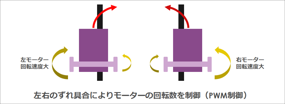
The most important aspects of this control are line detection and motor control. Therefore, in order for the car to always run on the line, the sensor at the front detects the position of the car in relation to the line, and the microcomputer controls the motor based on that signal.
To put it simply, if only the right sensor detects the black line, the left motor is rotated more strongly, and if only the left sensor detects the black line, the right motor is rotated more strongly. By making this control more finely, we aimed to make the running as smooth as possible. In reality, the running was a bit jerky, but it was able to run firmly on the line.
Key points
Next, I'd like to introduce some of the points I came up with when building this line tracing car.
That is, to change the speed manually like a manual car. One of the reasons is that I like cars, but by changing the speed, I aimed to run at the optimal speed for the course. The method is simple, but I installed three feedback resistors in the DC/DC converter in front of the motor and made it possible to supply three types of voltage with a switch.
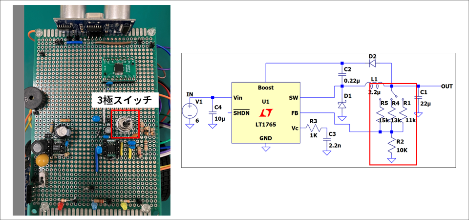
As mentioned in the article "5th DC/DC Converter Evaluation", when checking the output waveform with an oscilloscope, we were able to output three types of voltage as intended. In addition, we were able to successfully change the speed of the car accordingly. It wasn't that difficult, but I was happy to achieve what I was aiming for.
Summary
Although it ended up being the last episode, I was able to successfully complete the line tracing car during the production training. In addition to the main power supply design, this training also involved programming, which allowed me to experience the difficulties of design and the challenges of making things, and I also learned a lot. In the future, I would like to use this experience to become an FAE that designers can rely on.
Finally, I would like to thank everyone who has read this far. Thank you very much!
The path to my first circuit design Article list
・ DC/DC converter board design
・ Implementation of DC/DC converter
・Bonus