- Semiconductor BusinessHOME
- Products and Services of Macnica,Inc.
-
technical information

-
Events and Seminars
- Handling Manufacturer
- Support
- Inquiry
- Click here to purchase products
- Semiconductor business e-mail magazine registration
![]()
![]() Narrow down by specifying conditions
Narrow down by specifying conditions
現在2191件がヒットしています。check

Hello. I'm Tonpa, a new FAE.
I joined Macnica as a new graduate and learned about circuit design and implementation while experiencing manufacturing through production training. When I was a student, I majored in organic chemistry, and since I started with no knowledge of electricity and electronics, I often struggled.
Therefore, in this article, I will introduce what I learned about circuit design and implementation while experiencing manufacturing through manufacturing training. Last time, we introduced the board design of the DC/DC converter, but this time we will introduce the mounting of the board.
Mounting board
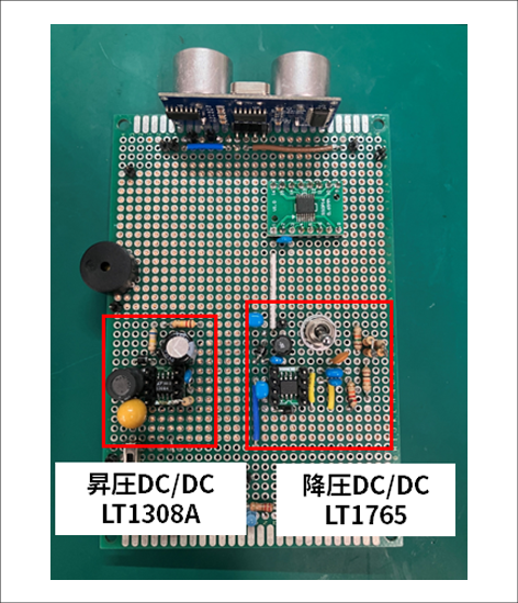
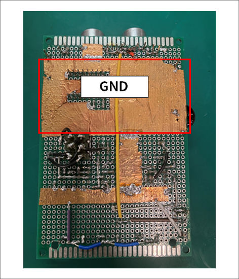
This is the actual board on which it was mounted.
As introduced in the design section, it is important to keep the hot loop wiring short for DC/DC converters, and by keeping this in mind, we were able to consolidate peripheral components near the IC. Also, regarding the GND, which is the reference voltage of the board, we were conscious of placing it widely on the back of the board (copper foil part) to ensure a stable GND. It was very difficult to consider and implement each component and its connection to GND like these.
From here, I will introduce the things I struggled with and the things I paid attention to when implementing it.
Thank you Flux
Since it was mounted on a universal board, all mounting was done by hand.
I had only learned a little in class when I was in junior high school, so I started with some trepidation, but the first soldering task was the most difficult.
that's right. Mounting the IC on the DIP conversion board.
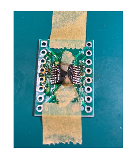
The photo on the left shows the installation in progress, and the photo on the right shows it after installation.
"Eh, it's really dirty. How did you get from this state to the clean state after implementation?"
I think many people think so.
However, there is nothing wrong with this dirty condition!
This is what happens when you use a trick taught to you by a senior employee.
I thought that I would not be able to do such detailed soldering, so I consulted my senior colleague, and he told me that it would be better to use flux. Flux is a soldering accelerator, and applying it makes it easier for solder to adhere to the land. When I actually used it, I found that the solder only adhered neatly to the lands, and there were almost no cases where it connected to the pins on the sides.
Another good thing about flux is that it can be easily washed off with alcohol. After mounting, it was easily removed using Kimwipe soaked with isopropanol. As a result, it was able to be reborn from a dirty state to a clean state as shown in Figure 2. Without this method, I don't think I would have been able to implement it at all (lol).
If you don't know about it, please use it.
Continuity check
Next is the continuity check, which I paid the most attention to when proceeding with the implementation.
It may be obvious, but continuity checks are essential when implementing. The confirmation method is simple; just place both terminals of the continuity checker on the measurement point as shown in Figure 3.
It is designed to make a sound when there is continuity, and no sound when there is no continuity.
I heard this "beep" sound so much that I hated it (lol).
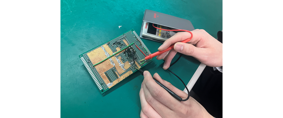
Figure 3: Continuity check
As the implementation progressed and we actually performed a continuity check, we found continuity between the power supply input and GND, indicating a short circuit. I thought it was a good idea to check, but there was one thing I regret. Since I noticed a short circuit with a lot of wiring already in place, it took me a while to pinpoint the source of the problem.
From this experience, I learned the importance of conducting detailed continuity checks, even though it is a bit tedious.
From then on, I was able to prevent mistakes by checking continuity after each soldering.
Also, it is necessary to perform a continuity check when mounting the IC introduced earlier on the DIP conversion board. When soldering fine details such as ICs, it is necessary to check continuity more carefully because there may be continuity with neighboring pins, or the amount of solder may be too small to establish continuity.
Summary
This time, we introduced the board mounting of DC/DC converters. I had a hard time with soldering, which I am not used to, but by using flux I was able to do detailed soldering. For those who don't know about flux, I highly recommend that you try using it. I also learned that continuity checks are important in order to prevent failures such as IC damage.
Next time, we will evaluate the mounted board. looking forward to.
The path to my first circuit design Article list
・ DC/DC converter board design
・Implementation of DC/DC converter
・ Bonus