- Semiconductor BusinessHOME
- Products and Services of Macnica,Inc.
-
technical information

-
Events and Seminars
- Handling Manufacturer
- Support
- Inquiry
- Click here to purchase products
- Semiconductor business e-mail magazine registration
![]()
![]() Narrow down by specifying conditions
Narrow down by specifying conditions
現在2168件がヒットしています。check

Hello, 3 I studied chemistry in college until the moon and forgot about Ohm's law mountain fudo is.
I joined Macnica as a technician and learned the basics of electrical and electronics while building a line tracing car through practical training. Production training We did this.
This will be a four-part series that will share what I learned and experienced through this production workshop, so I hope you will read it with a kind eye.
This blog is a continuation of the article on building a line tracing car from a power source (DC/DC converter specification review).
Summary of previous episodes
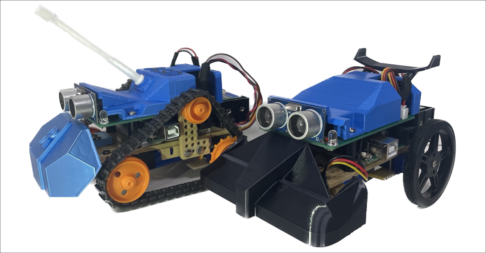
When I joined Macnica as an engineer, I learned about electrical and electronics through manufacturing training, which has traditionally been handed down as a gateway to success for newcomers. Here is the completed drawing of the line tracing car I made this time.
In the previous blog, we examined the specifications of the DC/DC converter, which is the heart of the target line tracing car. As a quick review, the specifications of this line tracing car are as shown in Figure 2, where a 9V battery is used as the power source, and the voltage is stepped down to 6V through a DC/DC converter. Since you will be soldering, the package should look like Figure 3 (with legs)!
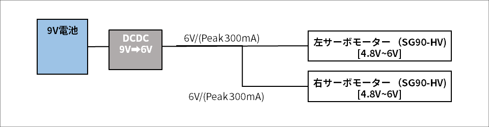
Figure 2: Line trace car specifications

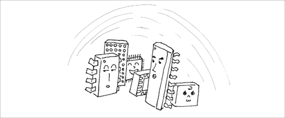
Figure 3: Semiconductor IC
Now, with this in mind, let's head deep into the forest in search of the important DC/DC converter IC.
Selection work
Let's look for it
First, let's take a look at Analog Devices' selection table of step-down DC/DC converters. Oh my god! That's too many products! When I heard that I would choose from these options, I was hesitant at first. The names and shapes all looked the same, so I was staring at them as if I had wandered into a jungle.
This selection table may all look the same, but although there are many types of Analog Devices DC/DC converters, each one has different characteristics. Of course, when it comes to power supplies, it's not just batteries, but when designing electronic equipment, a DC/DC converter that matches the specifications desired by the designer is selected. That's why there are so many types. If you look at each one one by one, it will be too late, so use a filter to narrow it down as shown in Figure 5.
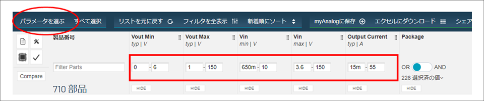
By customizing the part surrounded by the red line to what you want, you can arrive at the IC you want.
For example, you can show or hide the necessary parameters yourself from the red circle and adjust them. Then, change the parameter numbers as shown in the red square to narrow down the products. However, since I was going to do some soldering this time, I wanted an IC like the one shown in Figure 2, so I chose an 8-Lead SOIC from the filter package. (I just learned from my senior)
When I selected it as shown in Figure 6, LT1765 came out.
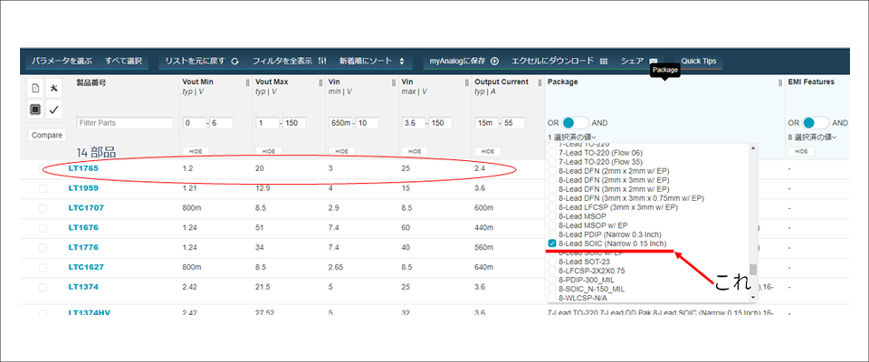
Well, looking at the status of LT1765, it seems like it can meet the specifications this time.
That's why I chose this IC. (LT1765)
In reality, you need to read the data sheet and check it thoroughly, but first of all, you want to check whether the input/output voltage and output current are within the specified range, and make sure to check the temperature rise calculation. . Of course, just connecting one LT1765 does not mean it will work as a DC/DC converter (honestly, I thought it would work at first). Since the LT1765 alone can be used in a variety of ways, it is necessary to make adjustments outside the IC to suit the usage that you want.
Try making a circuit
Let's start creating a circuit using the LT1765.
However, as someone who had never created a circuit before, the first thing he created was a DC/DC converter circuit, and he couldn't even imagine how it would work, so he learned how to build each IC one by one with the help of his seniors. I had to decide on the values of the surrounding inductors, capacitors, and resistors. However, since creating a circuit from scratch is extremely difficult, I decided to use the evaluation kit at the bottom of the LT1765 page as a reference, as shown in Figure 7.

Figure 7
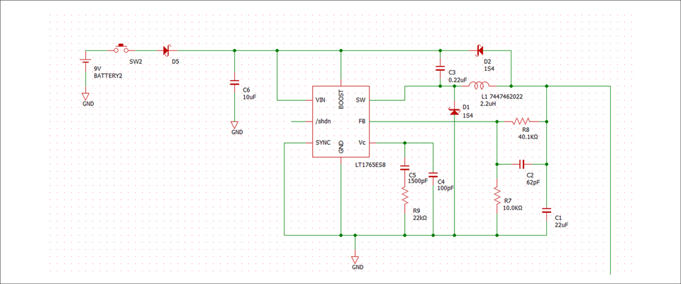
This evaluation kit is for engineers to evaluate how the IC actually works and whether there are any problems with their specifications before placing a large order. This includes a lot of information on components other than ICs and circuits. Using this page as a reference, I first converted the LT1765 evaluation board into my own circuit. I carefully looked at the application information in the data sheet and calculated the constants for the inductor and feedback resistor, and the circuit for the line tracing car was completed. (Figure 8)
There is also an article summarizing the calculation in detail on our website.
・ Constant calculation and precautions for step-down DC/DC converter
When I think about it now, Figure 8 is a very basic and faithful circuit, but at the time it was a completely complete circuit for me. (It took a long time)
Next, we will use this circuit to prepare the DC/DC converter that is the heart of a line trace car.
implementation plan
The circuit created as shown in Figure 8 must be soldered to the universal board according to the circuit, otherwise the line tracing car will not be able to stand at the starting point!
This is where we start making line tracing cars.
However, I've only ever done soldering in junior high school technology class. As I continued to study, I learned that the smaller the circuit area, the better, so I was very nervous about detailed soldering. Yes, even though it follows the circuit, a DC/DC converter can be good or bad depending on how it is implemented. For example, if a single wire is too long, it becomes both inductance and resistance. It would be a problem to have something like that in a place where it's not needed on the circuit.

Figure 9: Image - If the route (wiring) is long, it will be a problem.
The layout of the power supply is very deep. My seniors taught me that amateurs are bound to fail, so I studied very carefully beforehand.
I've read the following sites quite a bit.
・ Power supply layout and EMI
-Hot Loop is Chi-Saku Chi-Saku
-The ground is spacious and sticky.
Keeping these things in mind, I wrote down the design drawings in my notes many times as shown in Figure 10.
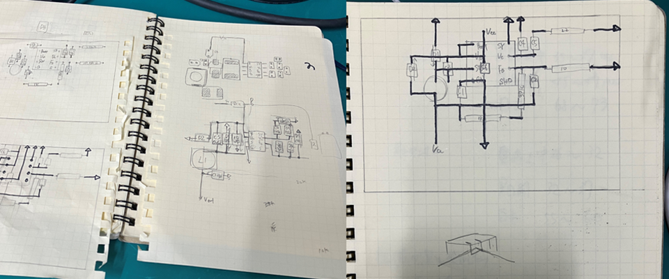
As shown in Figure 10, I used the squares on the notepad as holes in the board and did a lot of trial and error. We spent three days working on determining which combination met the power supply layout requirements and was the most compact.
Above all else, I had a strong desire not to fail, so I carefully and carefully wrote down the blueprints...
I didn't have anyone pass the test, and I couldn't figure it out until I tried it out, so I decided to try my hand at it until I was satisfied with it myself, so I decided to solder using Figure 10.
The detailed soldering work will be in the next work!
next time
Next time, we will actually solder and operate the DC/DC converter and its peripheral circuits that we designed this time! After that, we will move on to adding other parts to make the line tracing car!
During the production training, I have the most fun memories of working with my hands. I want to write stories that will make the readers want to create something as well ^0^
This was the memorable second episode of Fudo, a rookie engineer.
List of articles on line tracing cars made from power supplies
・ DC/DC converter specification study
・DC/DC converter implementation preparation edition