![]()
![]() Narrow down by specifying conditions
Narrow down by specifying conditions
現在2003件がヒットしています。check

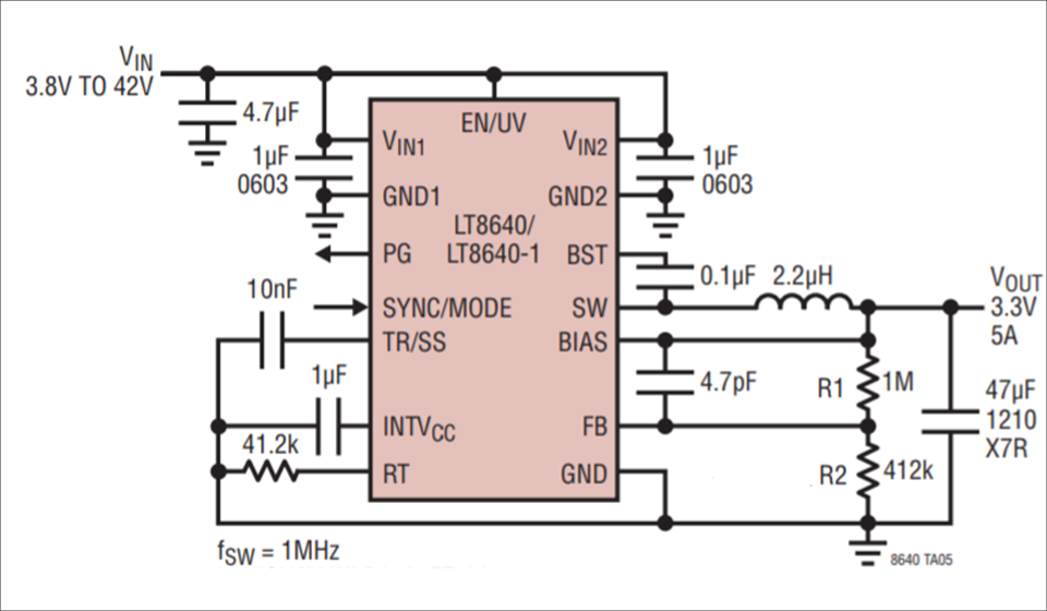
In this article, we will use the LT8640, a synchronous step-down DC/DC converter with a built-in power element, to explain the selection (calculation method) of the following peripheral constants.
・Dividing resistance to set the output voltage
・Switching frequency setting
・Inductor
・Input capacitor
・Output capacitor
Along with the constant calculation, we will also explain the basic points to note in component selection and component placement.
Let's learn DC/DC converter constant calculation with LT8640!
Designing a power supply circuit is often thought to be difficult, but selecting circuit constants is not that difficult.
If it is a step-down DC/DC converter, it is possible to select the constants based on the contents introduced here.
(Just in case, please design while referring to the data sheet of the selected model number.)
For example, consider the case where input VIN=12(V) output VOUT=3.3(V) load current IOUT=4(A) is desired.
Considering the 80% derating, select a product with a load current of 5(A) [=4(A)÷80%].
* Derating is an indicator of how much margin to design against the rating.
Setting the output voltage
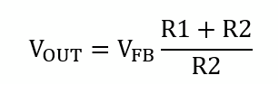
The output voltage (VOUT) can be set from the voltage dividing resistors R1 and R2 and the feedback voltage (VFB) as shown in the following formula.
Find R2 when the output voltage is 3.3V with R1 set to 1MΩ.
The feedback reference voltage for the LT8640 is calculated by substituting VFB = 0.97 into the following equation:
* Please check the data sheet for the feedback and reference voltages, as they differ depending on the product.
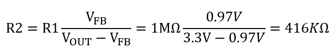
When calculated, R2 is 416KΩ, so select 412KΩ from the E96 series.
I often think that it is good as long as the voltage division ratio is correct when selecting the voltage dividing resistors. I get a question, but it's ng.
There is a recommended range for the voltage dividing resistor, so please refer to the recommended circuit example in the data sheet when selecting the resistor value.
switching frequency
The switching frequency of the LT8640 can be set from 200kHz to 3MHz.
Since we don't want to lower the efficiency while increasing the frequency and downsizing, we will use it with the 1MHz setting.
The value of resistor RT for frequency setting can be calculated by the following formula.
*Since the switching frequency setting method differs depending on the product, please check the data sheet for the calculation formula.
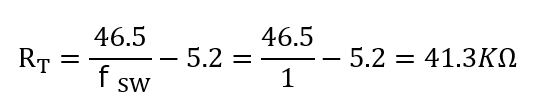
The unit of resistor RT is KΩ and the unit of switching frequency fsw is MHz.
When calculated, RT=41.3KΩ, so select 41.2KΩ from the E96 series.
Inductor selection
When selecting an inductor, determine the inductance using the following formula.
The inductor current is 4A for a real load, but the 5A rating for the LT8640 is used for calculations.
ΔIL is the ripple current of the inductor, so it should be 40% of the maximum load current.
Also, Vin(max) is calculated with 42V, which is the upper limit of the actual specification.
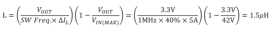
From the calculation, the inductance value should be 1.5μH or more.
In order to improve efficiency and reduce ripple voltage at light loads, 2.2μH is selected in the data sheet recommended circuit. Note that if the inductance value is too large, the load response will deteriorate.
When selecting an inductor, pay attention to the rated current and saturation current in addition to the inductance value.
Pay attention to the placement of the input capacitor
Input capacitors are placed for power-to-GND decoupling and for filtering the top MOSFET source current. To do this effectively, take care to place the input capacitors as close as possible to the VIN and GND pins (see red circles in Figure 2). Since the LT8640 has two VIN pins, it is important to place low ESR 1uF capacitors close to VIN1 and VIN2.
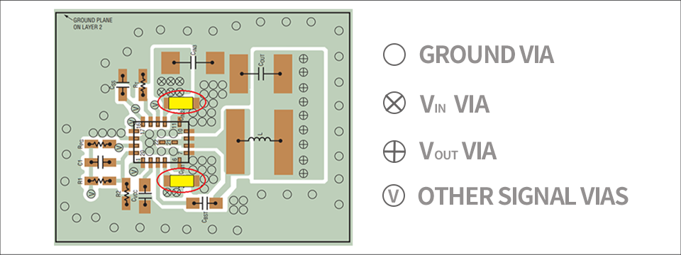
Place a 4.7uF ceramic capacitor on the power line that connects VIN1 and VIN2 together, as recommended in the datasheet.
Use ceramic capacitors with X7R or X5R characteristics. For general usage, these input capacitors alone are fine, but depending on your application, add capacitors while paying attention to the contents of the next power supply column article.
[Power supply column]
Part 1 Sounds coming from the DC/DC converter!
Part 2: Long wiring is the culprit?
output capacitor
For the output capacitor, refer to the circuit diagram constants listed in the "Typical Applications" section of the datasheet. Consider adding a capacitor if you want to improve load response characteristics or ripple.
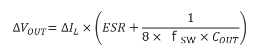
Please refer to the following formula for the calculation formula of the ripple voltage at that time.
This formula is a calculation formula for an ideal state and does not consider the inductance component on the board or the ESL of the capacitor.
Therefore, it may differ greatly from the measurement result of the actual machine.
Others
soft start
Soft start can be set by the capacitance of the capacitor connected to the TR/SS pin.
This makes it possible to set the slope (time) at which the output voltage rises.
The relational expression between the capacitor to be connected and the rise time varies depending on the output voltage setting, so please check using LTspice or an evaluation board.
For how to use LTspice, please refer to "Let's use LTspice!" or take a free seminar.
Phase Margin Adjustment
The compensation network for adjusting the phase margin of the LT8640 is integrated into the IC.
If adjustment is necessary, do so with a capacitor connected between the FB pin and VOUT.
In the LT8640, when the FB resistance value is large like this time, the capacitor value should normally be 4.7pF to 22pF.
When adjusting, do so while measuring the phase margin.
Others
・The capacitor connected to the BST pin is for the bootstrap circuit. Please connect 0.1uF according to the data sheet.
・The capacitor connected to INTVCC is for stabilizing the internal power supply (INTVCC). Please connect 0.1uF according to the data sheet.
This time, we have explained the constant calculation of a general step-down DC/DC converter.
For peripheral components not described here, please refer to the datasheet of the product you are using.
If you would like to know more about the contents of this article, please take the "Power Supply Design Seminar" in the recommended seminars.
Click here for recommended seminars/workshops
[Online Seminar] Analog Solution Power Supply Design Seminar <free>
[Online Seminar] Analog Solution Thermal Design Seminar <Free>
Click here for recommended articles/materials
Click here to purchase products
Inquiry
If you have any questions regarding this article, please contact us below.
Analog Devices Manufacturer Information Top
To return to the Analog Devices manufacturer information top page, please click below.