- Semiconductor BusinessHOME
- Products and Services of Macnica,Inc.
-
technical information

-
Events and Seminars
- Handling Manufacturer
- Support
- Inquiry
- Click here to purchase products
- Semiconductor business e-mail magazine registration
![]()
![]() Narrow down by specifying conditions
Narrow down by specifying conditions
現在2168件がヒットしています。check
![[Introduction to accelerometer] Let's use the tap detection function](/business/semiconductor/articles/Article_136493_cover.png)
In the [Introduction to Accelerometer] series, we will explain the basic usage and application methods, focusing on analog devices' accelerometers. In the previous article, we introduced the "self-test function" using the accelerometer "ADXL345" and "Arduino". In this article, we will introduce the "trigger function" installed in the ADXL345.
[Introduction to accelerometer] Click here for the series list
trigger mode
Feature overview
The trigger function introduced this time is a combination of the "FIFO function" and "activity detection function" introduced in the previous article.
Trigger means "cue, cause, event", and by using "active detection" (also inactive detection) as a trigger, FIFO can be used effectively. For applications that do not need to acquire real-time acceleration data, it can be used as an event logger that records data before and after the time when activity was detected.
As an image, it becomes an image like "SINGLE trigger" of an oscilloscope, and it is possible to analyze the state before and after the trigger event.
As an example of application, we can think of monitoring the status of transportation in a logistics system. For example, if a certain large acceleration occurs during the transportation of cargo by truck or aircraft, it will be possible to record the acceleration data before and after that log. Also, if acceleration data is acquired continuously for a long time, the memory capacity to hold the data may be limited. Therefore, it is possible to achieve a long data log by recording only the data when an event occurs.
Operation description
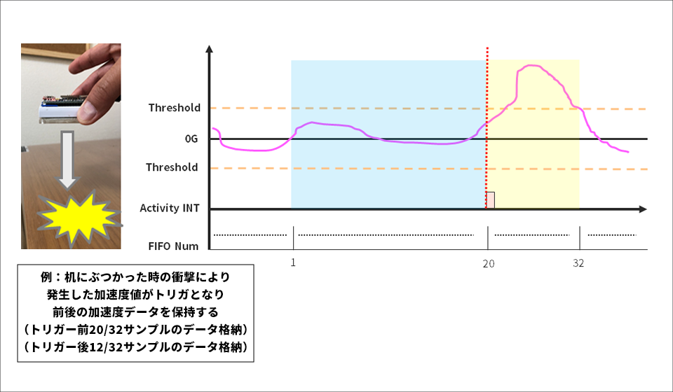
The ADXL345 FIFO can store up to 32 samples of X, Y, and Z axis acceleration data. With the trigger function, the number of data set in the "Sample_Num" register out of 32 samples is retained by the "active interrupt" that occurs when the acceleration exceeds a certain threshold, and the stored data before that is automatically discarded. There will be space in the FIFO. New data is then added as the FIFO is emptied until it is full. This motion allows you to keep acceleration data before and after the trigger event occurs.
I have created an image diagram below. The acceleration generated when the accelerometer hits the desk becomes a trigger signal, and the data before and after is stored in the FIFO. In this way, it becomes possible to use the event logger.
Please check the data sheet and application note for details.
Let's use the trigger function
We will create a sample program for the "trigger function" using the acceleration sensor "ADXL345" and the hardware open platform "Arduino".
Things to prepare
Here is what I prepared to evaluate the accelerometer this time.
・PC with Arduino IDE installed (Download Arduino IDE from here)
・ Arduino Nano compatible board
・Others (USB cable (for Arduino and PC connection), breadboard, wires)
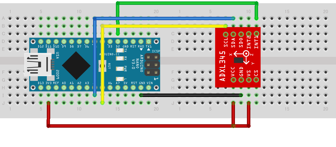
Combine the above parts to form a circuit as shown in the figure below. Power supply to Arduino Nano is supplied by USB bus power from PC. The ADXL345 supports SPI and I2C interfaces, but this time we will use the I2C interface. It also uses the INT1 pin of the interrupt pin.
Program content
In order to utilize the trigger function, configure settings related to the FIFO setting and activity detection function. The specific settings are described below.
・The ACT_INACT_CONTROL register (address 0x27) selects the AC/DC coupling mode and sets the X, Y, and Z axes to be enabled.
This time I enabled AC coupling mode and all axes.
• The THRESH_ACT register (address 0x24) sets the acceleration threshold for activity detection.
The scale factor is 62.5mg/LSB, and this time we set the threshold to ±2g, assuming a light impact on the desk.
・The FIFO_CTL register (address 0x38) sets the FIFO mode and the number of stored samples. Since it is Trigger mode this time, set BIT[7:6]=0x02.
In addition, BIT[4:0] specifies the number of data before the trigger event that is held in the FIFO buffer when the trigger event occurs.
I set it to 20 samples this time.
The trigger event occurrence status can also be checked in the FIFO_STATUS register (address 0x39). Also, when reactivating the function after trigger detection, reset the trigger. The method is to set the device to bypass mode and then set it back to trigger mode. Note that putting the device into bypass mode clears the FIFO, so the data in the FIFO must be read before putting the device into bypass mode.
After detecting the interrupt of the trigger event, this program acquires the stored data and displays the acquired data on the Arduino serial monitor. You can download the project file created with the Arduino IDE, so if you are interested, please get it from the "Document Download" below.
operation check
Let's check the operation with the created program. It was confirmed that the data of 20 samples before and 12 samples after (total 32 samples) were retained by triggering the change in acceleration that occurred when the device was hit against the desk. When I graphed this data, I was able to confirm the data before and after the impact.
Download the sample code verified this time
We provide the Arduino project file that we implemented this time. Please apply from here and give it a try.
About Accelerometer ADXL345
The ADXL345 used this time is a 3-axis digital output acceleration sensor. The main features are as follows.
・A standard accelerometer that is very easy to use with built-in ADC, operation function block, and FIFO
・Acceleration data adopts general I2C/SPI in digital serial method
・The 3-axis type sensor is a rectangular coordinate (X, Y, Z), and the acceleration acting on each axis can be obtained.
・The maximum detectable acceleration can be set in the range of 2g to 16g, and the sampling range is as wide as ~3.2kHz, so it can be applied to various applications such as impact, tilt, and motion detection.
・Flexible mode to reduce current consumption
For more information on the ADXL345, visit www.adxl345.com. data sheet Please refer to. Also, this accelerometer is very easy to use, so if you want to evaluate an accelerometer from now on, please try it on the evaluation board.
At the end
If you have any questions about the contents of this article, or if you have any problems with selecting or using accelerometers, please contact us from the following.
Analog Devices Manufacturer Information Top
If you want to return to Analog Devices Manufacturer Information Top, please click the button below.
![[Introduction to accelerometer] Thumbnail image of Let's use the interrupt function](/business/semiconductor/articles/9d56e574e3a24bcf3f076e91d90f4a53.png)