- Semiconductor BusinessHOME
- Products and Services of Macnica,Inc.
-
technical information

-
Events and Seminars
- Handling Manufacturer
- Support
- Inquiry
- Click here to purchase products
- Semiconductor business e-mail magazine registration
![]()
![]() Narrow down by specifying conditions
Narrow down by specifying conditions
現在2186件がヒットしています。check
![[Introduction to accelerometer] Let's use the tap detection function](/business/semiconductor/articles/Article_136305_cover.png)
In the [Introduction to Accelerometer] series, we will explain the basic usage and application methods, focusing on analog devices' accelerometers. In the previous article, we introduced the "tap detection function" using the accelerometer "ADXL345" and "Arduino". In this article, we will introduce the "active/inactive detection function" built into the ADXL345.
[Introduction to accelerometer] Click here for the series list
Active/inactive detection function
Feature overview
The activity/inactivity detection function of the ADXL345 is a function that recognizes a change in a specific acceleration and generates an interrupt. This feature is sometimes called motion detection. It is possible to detect the presence or absence of a specific motion based on the acceleration threshold and acceleration duration set by the user.
By using the active/inactive function, it is possible to add new value to the application. Below are some application examples.
Example 1: "Wake-up switch function" that wakes up the device from the standby state by lifting a handheld device such as a mobile phone from the desk.
In addition, the "off switch function" automatically returns to the standby state when it is put back on the desk.
Example 2: "Misplacement prevention function" that detects when the device has not been used for a certain period of time and issues an alert
Example 3: "Security function" that installs acceleration sensors on windows and doors to detect changes in acceleration due to external shocks and vibrations and issue alerts.
Also, the active/inactive function can generate an interrupt signal. Therefore, it is possible to put the host CPU into a sleep state until an interrupt is detected, and the power consumption of the system can be reduced.
Operation description
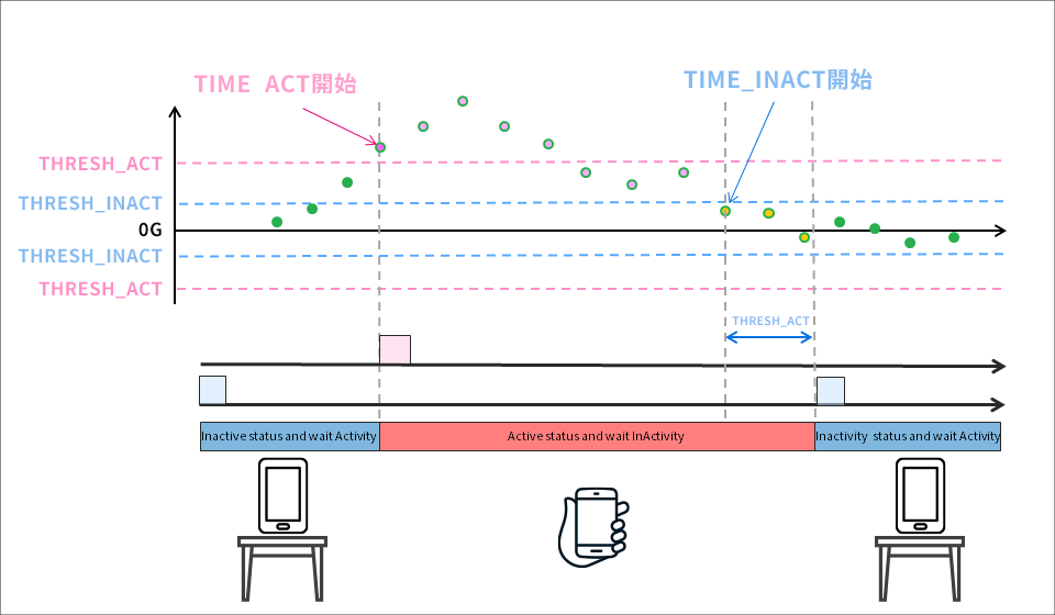
"Active interrupt" generates an interrupt when the user-defined activity threshold is exceeded. "Inactivity interrupt" outputs an interrupt when the inactivity threshold and the set duration are met.
I have created an image diagram below. An active interrupt occurs when the acceleration caused by lifting the device from the desk top exceeds the THRESH_ACT threshold. Also, when the device is placed back on the desk, the acceleration falls within the THRESH_INACT threshold. And if it continues for TIME_INACT, an inactivity interrupt will occur. Also, if LinkMode is enabled, it will be set to detect only active detection after inactivity. Therefore, it is possible to prevent the continuous occurrence of inactive interrupts and active interrupts. Please see the datasheet for details.
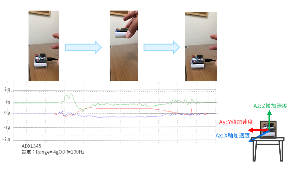
I took the acceleration data when actually lifting the device. As shown in the figure below, when the accelerometer is lifted vertically, changes in acceleration can be seen on the Z axis. In this case, I think it is possible to set the detection threshold to around +0.5g from the initial value to the activity threshold. Assuming the movement to be detected and the usage environment, consider the acceleration axis and acceleration threshold to be set.
Let's use the activity/inactivity detection function
We will create a sample program for the "active/inactive detection function" using the acceleration sensor "ADXL345" and the hardware open platform "Arduino".
Things to prepare
Here is what I prepared to evaluate the accelerometer this time.
・PC with Arduino IDE installed (Download Arduino IDE from here)
・ Arduino Nano compatible board
・Others (USB cable (for Arduino and PC connection), breadboard, wires)
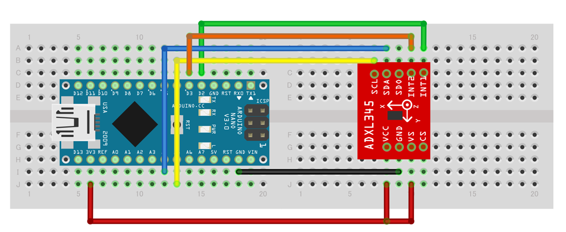
Combine the above parts to form a circuit as shown in the figure below. Power supply to Arduino Nano is supplied by USB bus power from PC. The ADXL345 supports SPI and I2C interfaces, but this time we will use the I2C interface.
Also, both the INT1 and INT2 interrupt pins are used.
Program content
In this program, we will detect both active and inactive functions. Therefore, it is necessary to set the related registers. The specific settings are described below. For details of registers, see data sheet Please confirm.
・The ACT_INACT_CONTROL register (address 0x27) selects the AC/DC coupling mode and sets the X, Y, and Z axes to be enabled.
This time I enabled AC coupling mode and all axes.
• The THRESH_ACT register (address 0x24) sets the acceleration threshold for activity detection.
The scale factor is 62.5mg/LSB, and 0.5g was set as the threshold this time.
• The THRESH_INACT register (address 0x24) sets the acceleration threshold for activity detection.
The scale factor is 62.5mg/LSB, and this time we set 0.125g as the threshold.
・The TIME_INAC register (address: 0x26) sets the duration after exceeding the inactivity threshold.
The scale factor is 1 sec/LSB (maximum 255 sec), and I set it to 4 sec this time.
・In the INT_MAP register (address: 0x2F), the interrupt function for the bit set to '1' is reflected in the INT2 pin.
This time I set the "inactivity interrupt" to the INT2 pin. Interrupt factors that are not set are reflected in INT1.
・BIT[4] of the INT_ENABLE register (address 0x2E) is assigned to activity detection, and BIT[3] is assigned to inactivity detection.
I enabled both this time. Also, by reading the IINT_SOURCE register, the interrupt source can be cleared.
• BIT[5] of the POWER_CTL register (address 0x2D) becomes the "Link" bit. With active and inactive features enabled
By setting the bit to '1', the active function can be suppressed until inactivity is detected. This time I set the Link bit.
The contents of the program are to set the registers of the ADXL345. After that, when an active interrupt is detected, output "Active detected" log to the Arduino serial console. Similarly, when an inactive interrupt is detected, the log of "InActive detected" is output. You can download the project file created with the Arduino IDE, so if you are interested, please get it from the "Document Download" below.
operation check
Let's check the operation with the created program. I left the device on my desk and when I picked it up it detected an active interrupt and logged "Active detected" to the console. Similarly, when it returned to the state where it was placed on the desk, an inactive interrupt was detected and a log of "InActive detected" was output.
Download the sample code verified this time
We provide the Arduino project file that we implemented this time. Please apply from here and give it a try.
About Accelerometer ADXL345
The ADXL345 used this time is a 3-axis digital output acceleration sensor. The main features are as follows.
・A standard accelerometer that is very easy to use with built-in ADC, operation function block, and FIFO
・Acceleration data adopts general I2C/SPI in digital serial method
・The 3-axis type sensor is a rectangular coordinate (X, Y, Z), and the acceleration acting on each axis can be obtained.
・The maximum detectable acceleration can be set in the range of 2g to 16g, and the sampling range is as wide as ~3.2kHz, so it can be applied to various applications such as impact, tilt, and motion detection.
・Flexible mode to reduce current consumption
For more information on the ADXL345, visit www.adxl345.com. data sheet Please refer to. Also, this accelerometer is very easy to use, so if you want to evaluate an accelerometer from now on, please try it on the evaluation board.
At the end
If you have any questions about the contents of this article, or if you have any problems with selecting or using accelerometers, please contact us from the following.
Analog Devices Manufacturer Information Top
If you want to return to Analog Devices Manufacturer Information Top, please click the button below.
![[Introduction to accelerometer] Thumbnail image of Let's use the interrupt function](/business/semiconductor/articles/9d56e574e3a24bcf3f076e91d90f4a53.png)