- Semiconductor BusinessHOME
- Products and Services of Macnica,Inc.
-
technical information

-
Events and Seminars
- Handling Manufacturer
- Support
- Inquiry
- Click here to purchase products
- Semiconductor business e-mail magazine registration
![]()
![]() Narrow down by specifying conditions
Narrow down by specifying conditions
現在2182件がヒットしています。check
![[Introduction to accelerometer] Let's use the interrupt function of the accelerometer](/business/semiconductor/articles/Article_135152_cover_re.png)
In the [Introduction to Accelerometer] series, we will explain the basic usage and application methods, focusing on analog devices' accelerometers. In the previous article, "Let's get accelerometer data", we introduced how to get accelerometer data using accelerometer "ADXL345" and "Arduino". In this article, we will introduce how to acquire data using the "interrupt function" of the ADXL345.
[Introduction to accelerometer] Click here for the series list
ADXL345 Interrupt Capability
The ADXL345 is a 3-axis digital output accelerometer. Equipped with a function to generate an interrupt by digitally calculating the acceleration data acquired inside the IC and judging the event. This function can reduce the processing load on the host side (microcomputer, etc.), enabling efficient system design.
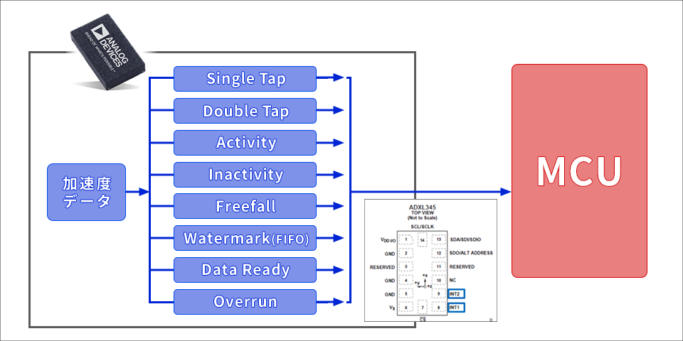
The ADXL345 has the following eight interrupt sources.
・DATA_READY: Interrupt occurs when new acceleration data is updated
・SINGLE_TAP: An interrupt occurs when a tap operation is detected (image of a mouse click operation)
・DOUBLE_TAP: An interrupt occurs when a double-tap operation is detected (image of mouse double-click operation)
・Activity: An interrupt occurs when the acceleration exceeds the set threshold range
・Inactivity : An interrupt occurs when the acceleration falls below the set threshold range.
・FREE_FALL : An interrupt occurs when a free fall is detected.
・Watermark: An interrupt occurs when the number of samples in the FIFO exceeds the specified value.
・Overrun: When unread acceleration data is updated to new data (In FIFO mode, interrupt occurs when FIFO becomes full)
In addition, the ADXL345 has dedicated pins (8th pin: INT1, 9th pin: INT2) that notify interrupts.
This allows design flexibility when selecting interrupt events.
Let's use the interrupt function
We will introduce an example using the "Data_Ready" interrupt using the acceleration sensor ADXL345 and the hardware open platform Arduino.
The operation outline of the Data_Ready interrupt is as follows.
・The timing at which acceleration data is acquired is set by the update rate register.
・New data is stored in the data register at the timing of the set update rate.
・If the DATA_READY interrupt is enabled, the result is reflected in the interrupt pin (INT1 or INT2) and the INT_SOURCE register, which is the interrupt status register, at the update timing.
By using the "Data_Ready" interrupt, the MCU on the host side can allocate resources to other processes while there is no update timing interrupt notification. In the case of battery drive, the MCU can be put to sleep to reduce power consumption.
Things to prepare
Here is what I prepared to evaluate the accelerometer this time.
・PC with Arduino IDE installed (Download Arduino IDE from here)
・USB cable (for Arduino and PC connection)
・ Arduino Nano compatible board
・Breadboard and wire
Combine the above parts to form a circuit as shown in the figure below. Power supply to Arduino Nano is supplied by USB bus power from PC. The ADXL345 supports SPI and I2C interfaces, but this time we will use the I2C interface.

Program content
In the program created this time, the following settings were made before setting the ADXL345 to measurement mode.
・Set the BW_RATE register (address 0x2C) to 100Hz and set it to 10msec (the default is 100Hz, so it can be omitted)
・Set BIT[7]=1 in the INT_ENABLE register (address 0x2E) to use the DataReady interrupt
(Refer to the datasheet for register details.)
After changing to measurement mode, the INT1 pin changes from low to high when the ADXL345 is updated with new acceleration data every 10ms.
When the Arduino detects the signal from INT1, it reads the INT_SOURCE register (address 0x30) to check the interrupt cause.
If BIT[7] of DataReady is 1, it means that the new data has been updated, so get the acceleration data.
(Regarding reading the INT_SOURCE register, there is no problem in omitting it in this case where multiple interrupt factors are not set.)
There is one point to note when using DataReady interrupts. The data register (Address 0x32) must be read to clear the interrupt condition. If the Arduino microcomputer is reset, the INT interrupt status may be retained, so it is recommended to perform a dummy read of the data register when initializing the ADXL345.
The project file created with Arduino IDE can be downloaded from "Download the sample code verified this time", so please download it if you are interested. Also, please refer to the previous article "Let's get accelerometer data" for how to get data without using Data_Ready.
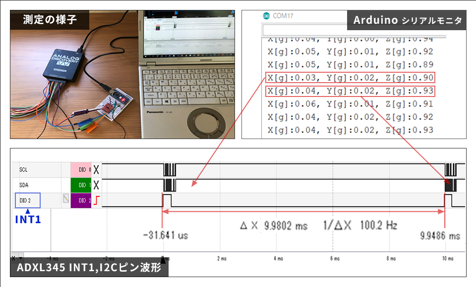
operation check
I checked the waveform of the INT1 pin using the logic analyzer function of AnalogDisovery. As shown in the figure below, it was confirmed that the signal level changed from Low to High at approximately the set cycle of 100Hz (10msec). Also, after accepting the interrupt signal, when the acceleration data was acquired, the INT pin changed from High to Low, so we were able to confirm that the interrupt notification was cleared.
In the Arduino program, after detecting an interrupt signal, we checked the cause of the interrupt and obtained X, Y, and Z acceleration data. Looking at the I2C communication waveform in the figure, the time required for this work was about 0.5 msec. In other words, by using the "DataReady" interrupt, you can do other processing for about 9.5msec out of 10msec. In future articles, I would like to introduce other interrupt functions such as the Free-Fall interrupt.
Download the sample code verified this time
We provide the Arduino project file that we implemented this time. Apply here and give it a try!
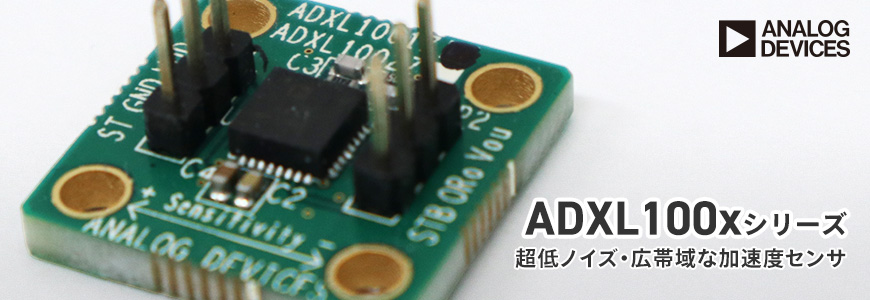
About Accelerometer ADXL345
The ADXL345 used this time is a 3-axis digital output acceleration sensor. The main features are as follows.
・A standard accelerometer that is very easy to use with built-in ADC, operation function block, and FIFO
・Acceleration data adopts general I2C/SPI in digital serial method
・The 3-axis type sensor is a rectangular coordinate (X, Y, Z), and the acceleration acting on each axis can be obtained.
・The maximum detectable acceleration can be set in the range of 2g to 16g, and the sampling range is as wide as ~3.2kHz, so it can be applied to various applications such as impact, tilt, and motion detection.
・Flexible mode to reduce current consumption
For more information on the ADXL345, please refer to the datasheet.
Also, this accelerometer is very easy to use, so if you want to evaluate an accelerometer from now on, please try it on the evaluation board.
At the end
If you have any questions about the contents of this article, or if you have any problems with selecting or using accelerometers, please contact us from the following.
Click here for recommended articles/materials
ADcmXL3021 High performance 3-axis MEMS sensor that can be installed with standard machine screws
[Introduction to accelerometers] ~Let's get accelerometer data~
Analog Devices Manufacturer Information Top
If you want to return to Analog Devices Manufacturer Information Top, please click the button below.