- Semiconductor BusinessHOME
- Products and Services of Macnica,Inc.
-
technical information

-
Events and Seminars
- Handling Manufacturer
- Support
- Inquiry
- Click here to purchase products
- Semiconductor business e-mail magazine registration
![]()
![]() Narrow down by specifying conditions
Narrow down by specifying conditions
現在2168件がヒットしています。check
![[Introduction to accelerometer] Let's use the interrupt function of the accelerometer](/business/semiconductor/articles/Article_135276_cover.png)
In the [Introduction to Accelerometer] series, we will explain the basic usage and application methods, focusing on analog devices' accelerometers. In the previous article, Let's use the interrupt function of the accelerometer, we introduced how to use the "interrupt function", which is one of the functions of the ADXL345, to acquire data. This time, I would like to explain how to use the FIFO function.
[Introduction to accelerometer] Click here for the series list
Understanding the FIFO Feature of the ADXL345
FIFO "First In First Out" refers to a structure in which the first stored data comes out first in a data storage area such as register memory. By using FIFO, you can have flexibility in communication timing between devices.
The ADXL345 has a 32-stage FIFO buffer that can hold up to 32 samples of 3-axis acceleration data for the X, Y, and Z axes. By using the sensor's built-in FIFO, the host processor can reduce the number of accesses to retrieve data, allowing it to focus on other tasks. In addition, by reducing the number of accesses, the host processor can be kept asleep for a longer period of time, and the power consumption of the system can be reduced.
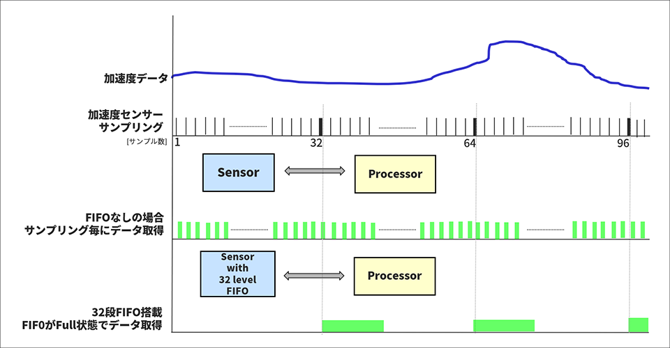
The figure below shows the image of communication between the accelerometer and processor with and without the sensor FIFO. As shown in the figure, the accelerometer performs sampling at regular intervals.
Without FIFO, the host processor would have to get data at every sampling and would always have to keep an eye on the data from the sensor.
On the other hand, if the FIFO is installed, the host processor can concentrate on other processing (for example, writing acceleration data to the SD card) because it is possible to retrieve data when the FIFO is full. , perform arithmetic operations on data, etc.). Also, from the viewpoint of current consumption, the number of times the host processor sleeps and wakes up each time data is acquired can be reduced, resulting in lower system power consumption.
The ADXL345h FIFO settings correspond to four modes that can be set with the FIFO_CTRL register.
① Bypass mode: FIFO not used (Default setting)
② FIFO mode: When FIFO is full, data is retained until data is read out
(In the full state, new acceleration data will not be updated. Also, reading the FIFO data will resume saving new data.)
③ Stream mode: The difference from FIFOMODE is that when the FIFO is full, new data overwrites the oldest data.
④ Trigger mode: Mode that can be used in combination with an active interrupt event
(By using the first active event that occurred in the interrupt factor, it normally operates in the same way as Stream mode, and after event detection, it operates in FIFO mode. Therefore, it is possible to save samples before and after the occurrence of an active event. I can.)
In addition, there are overrun interrupt and watermark interrupt functions as interrupt functions for knowing the FIFO status.
① Overrun interrupt: An interrupt occurs when the FIFO becomes full (32 samples)
② Watermark interrupt: An interrupt occurs when the specified number of samples is reached.
Selecting the FIFO mode and interrupt function enables flexible design according to the user application.
Please refer to the data sheet and Application Note [AN-1025] for details about FIFO.
Let's use the FIFO function
Let's use the FIFO function using the acceleration sensor ADXL345 and the hardware open platform Arduino.
Things to prepare
Here is what I prepared for evaluating the accelerometer.
・PC with Arduino IDE installed (Download Arduino IDE from here)
・USB cable (for Arduino and PC connection)
・ Arduino Nano compatible board
・Breadboard and wire
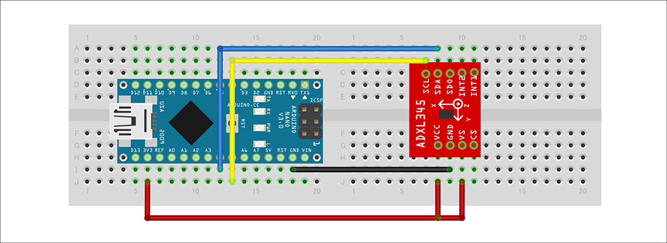
Combine the above parts to form a circuit as shown in the figure below. Power supply to Arduino Nano is supplied by USB bus power from PC. The ADXL345 supports SPI and I2C interfaces, but this time we will use the I2C interface.
Program content
Create a program that stores 16 samples of 3-axis acceleration data of X, Y, Z in the FIFO buffer of ADXL345, receives the interrupt signal issued at that time with Arduino, and then acquires the stored data collectively Did.
We need to set some registers to take advantage of the FIFO functionality. The main contents are described below.
◎ BW_RATE register (address 0x2C):
Update rate setting register. In this example, the default is 100Hz (10msec).
◎ FIFO_CTL register (address 0x38):
BIT[7:6] correspond to FIFO mode setting. Since FIFO mode is used this time, set BIT[7:6]=0x01. In addition, BIT[4:0] are the setting bits for the number of samples. In FIFO mode, the number of data for generating a watermark interrupt is 16 this time, so set BIT[4:0] = 0x0F.
◎INT_ENABLE register (address 0x2E):
This is an interrupt enable setting register. Set BIT[2]=1 to enable Watermark interrupt.
With the above settings, the interrupt generation timing is "update rate * number of samples = 10msec * 16 = 160msec", and the INT1 pin changes from Low to High when an interrupt is detected.
After detecting the change of the INT1 pin, the program reads the INT_SOURCE register (address 0x30) to check the interrupt source. If the Watermark interrupt BIT is 1, read ADXL345_FIFO_STATUS (address: 0x39) to check the number of samples stored in FIFO. After that, the data for the stored samples is acquired.
Data saved in FIFO is retained even in Standby mode. If you want to clear all at once, you need to select Bypass mode with the FIFO_CTL register.
Please refer to the data sheet and Application Note [AN-1025] for details and usage of the ADXL345 registers.
You can also download the project file created with the Arduino IDE, so if you are interested, please get it from the "Document Download" below.
operation check
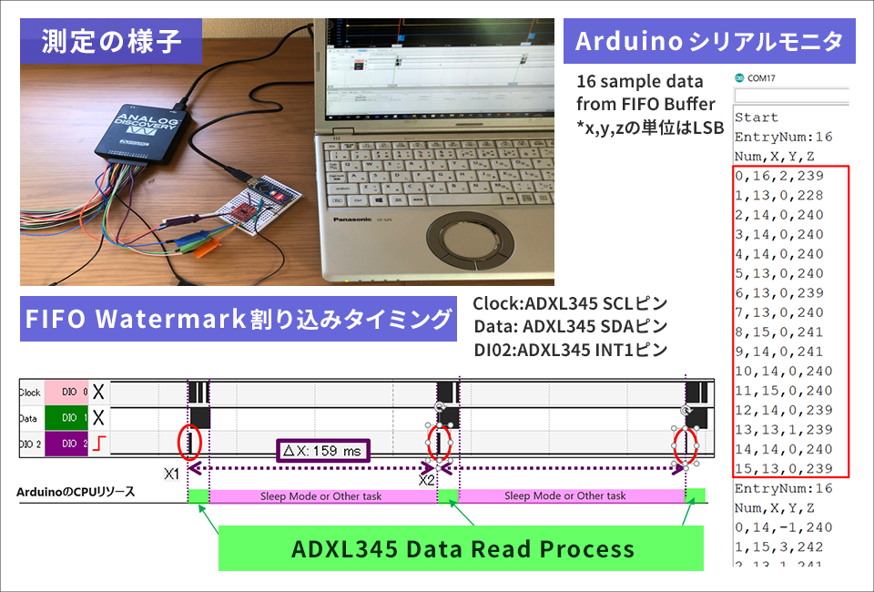
As shown in the figure below, it was confirmed that 16 samples of acceleration data for the three axes of X, Y, and Z were read on the serial monitor. Also, when using AnalogDisocvery to monitor the INT pin, I2C clock pin and data pin, it can be confirmed that the INT1 pin changes from Low to High at 160msec when the set number of samples is reached. Also, as shown in the figure, the Arduino batch retrieves the data stored in the FIFO after the interrupt (green part in the figure), so it is possible to secure a long time until the interrupt comes (pink part in the figure). , it is possible to allocate resources to sleep operations or other work.
In the previous article "Let's use the interrupt function of the accelerometer", we used the DataReady interrupt to acquire sampling data every 10msec. Please refer to this as well.
Also, there are other useful ways to use the FIFO function. I would like to introduce an example of FIFO trigger mode combined with active interrupt in the future.
Averaging process using FIFO
There are other benefits of having a FIFO built-in on the sensor side. In general, data from sensors is difficult to maintain a constant value due to noise, but by averaging multiple sample data, stable results can be obtained. Therefore, by having a FIFO buffer on the sensor side, by acquiring multiple data at once and averaging them at the same time, the host processor does not need to always hold the number of data for averaging, so the result You can reduce the amount of RAM.
For example, the Arduino Nano microcomputer used in this experiment has a RAM area of only 2Kbytes. Acceleration data consists of 2 bytes, and 6 bytes for 3 axes. Furthermore, if 32 pieces of data are to be held, 32 x 6 bytes = 192 bytes of capacity is required, which occupies about 10% of the total. Therefore, in small-scale microcontrollers, the memory capacity of the host can be used efficiently by utilizing the FIFO built into the sensor.
Download the sample code verified this time
We provide the Arduino project file that we implemented this time. Apply here and give it a try!
About Accelerometer ADXL345
The ADXL345 used this time is a 3-axis digital output acceleration sensor. The main features are as follows.
・A standard accelerometer that is very easy to use with built-in ADC, operation function block, and FIFO
・Acceleration data adopts general I2C/SPI in digital serial method
・The 3-axis type sensor is a rectangular coordinate (X, Y, Z), and the acceleration acting on each axis can be obtained.
・The maximum detectable acceleration can be set in the range of 2g to 16g, and the sampling range is as wide as ~3.2kHz, so it can be applied to various applications such as impact, tilt, and motion detection.
・Flexible mode to reduce current consumption
For more information on the ADXL345, please refer to the datasheet.
Also, this accelerometer is very easy to use, so if you want to evaluate an accelerometer from now on, please try it on the evaluation board.
At the end
If you have any questions about the contents of this article, or if you have any problems with selecting or using accelerometers, please contact us from the following.
Click here for recommended articles/materials
ADcmXL3021 High performance 3-axis MEMS sensor that can be installed with standard machine screws
Analog Devices Manufacturer Information Top
If you want to return to Analog Devices Manufacturer Information Top, please click the button below.

![Thumbnail image of [Introduction to Accelerometer] ~Let's get accelerometer data~](/business/semiconductor/articles/Article_134574_thumb_1.png)