- Semiconductor BusinessHOME
- Products and Services of Macnica,Inc.
-
technical information

-
Events and Seminars
- Handling Manufacturer
- Support
- Inquiry
- Click here to purchase products
- Semiconductor business e-mail magazine registration
![]()
![]() Narrow down by specifying conditions
Narrow down by specifying conditions
現在2189件がヒットしています。check


hello.
My name is Hanako Altera and I provide technical support for Altera® FPGA products at Macnica.
When performing functional simulation using Questa* - Altera® FPGA Edition, you not only want to monitor the signals at the pin level of the Altera® FPGA, but also want to view the internal signals of the FPGA, right?
There are several ways to display FPGA internal signals in the Wave window during simulation:
[A] Describe and display in the testbench
[B] Displaying with Questa* - Altera® FPGA Edition GUI
This time, we will be looking at [B] Questa* - Altera® FPGA Edition. This article will show you how to display FPGA internal signals in the Wave window using GUI operations.
In the second half, there will also be a "Hanako's little points ♪" corner for NativeLink simulation users.
By using this method, the work efficiency of the simulation will be improved. Give it a try!
sample design
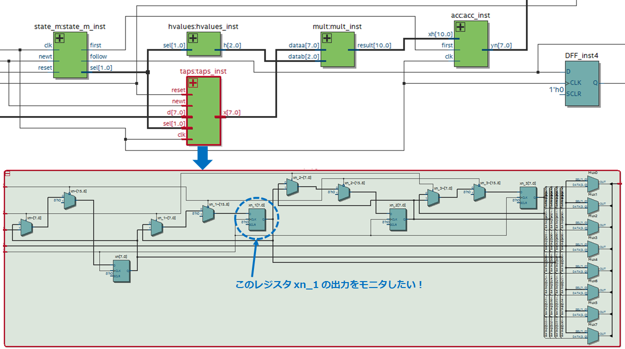
The figure below shows a sample design displayed in the Quartus® Prime RTL Viewer.
A submodule of this design is taps (instance name: taps_inst).
This time, we will guide you with an example of referring to the output of the internal register xn_1 (7bit) of taps.
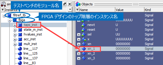
Note that the instance name of the FPGA top-level module in the testbench is fpga.
Questa* - Altera® FPGA Edition GUI Operation
① In Questa* - Altera® FPGA Edition, complete the compilation and loading of the source (Start Simulation).
② Select the desired instance (taps_inst) from the hierarchical view of the design displayed in the Srtructure window (sim tab).
(3) The ports and internal registers of the specified instance are displayed in the Objects window.
From here, drag and drop the desired signal (xn_1) into the Wave window.

④ Run the simulation.
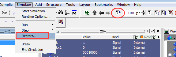
If you add an internal signal after running the simulation,
Reset the simulation (Simulation menu > Run > Restart or icon) and run again from 0ns.
A little point of Hanako♪
If you are running a simulation with NativeLink, it will automatically run through the simulation.
If you add an internal signal to the Wave window, after completing the simulation once with NativeLink, reset (Restart) and start simulating again from 0ns, so it's a double hassle, right?
So let's add a script to add internal signals to the Wave window beforehand!
Create an original script that adds the signal and submit it to Quartus Prime.
① Open a new text editor.
(2) Specify the signal to be registered in the Wave window using the add wave command.
* (asterisk) to specify all ports on the testbench.
add wave *Internal signals specify a hierarchy path using the instance name of each hierarchy.
For example, to refer to the output of register xn_1 in taps:taps_inst, write as follows.
add wave /fpga/taps_inst/xn_1So that's it.
(3) Describe the run command that instructs the execution of the simulation.
run -allIf you want to specify the execution time, say something like rum 500 ms.
④ Save the script file with the extension .do. (The previous commands are summarized below)
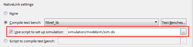
add wave * add wave /fpga/taps_inst/xn_1 run -all⑤ In Quartus Prime Assignments menu > Settings > EDA Tool Settings > Simulation > NativeLink settings,
Enable the Use script to set up simulation option and additionally register the original script created from the browse button.
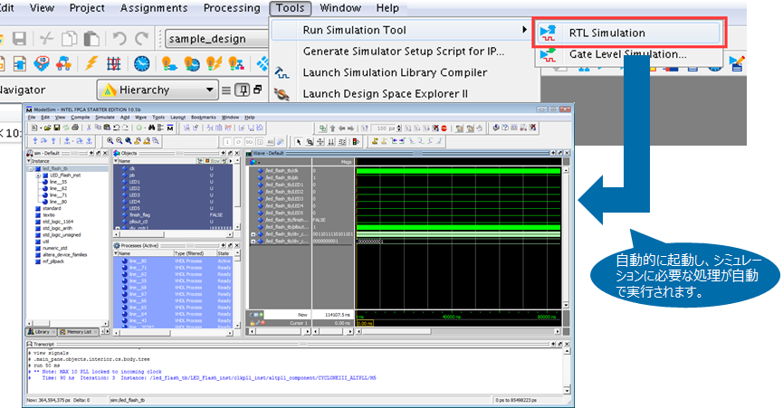
⑥ Select Tools menu > Run Simulation Tool > RTL Simulation to run the simulation.
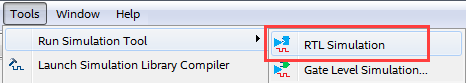
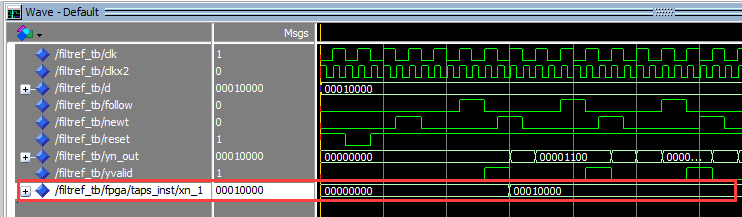
The specified internal signal is added to the Wave window and the simulation is running.
hey! It's easy.
Please practice immediately.
This time, we introduced how to monitor internal signals of a design using Questa* - Altera® FPGA Edition.
There is also a way to write this series of operations in the testbench.
With this, internal signals can be monitored without GUI operation, further improving debugging efficiency!
For more information, see How to Monitor Internal Signals of Altera® FPGAs in Simulation (How to Write a Testbench).
Click here for recommended articles/materials
Let NativeLink solve your FPGA function simulation
ModelSim® - Altera® FPGA Edition - RTL Simulation Methodology