- Semiconductor BusinessHOME
- Products and Services of Macnica,Inc.
-
technical information

-
Events and Seminars
- Handling Manufacturer
- Support
- Inquiry
- Click here to purchase products
- Semiconductor business e-mail magazine registration
![]()
![]() Narrow down by specifying conditions
Narrow down by specifying conditions
現在2168件がヒットしています。check
![[Passive Components (LC) Basic Course Series] LC Basics - Part 3: Inductor Characteristics](/business/semiconductor/articles/136570_wurth_article_cover_ver2.png)
Inductors and capacitors are essential components in electronic circuits. I will explain the basic role of its operation.
The contents of this time will be Part 3 "Characteristics of Inductors".
If you want to see other articles, there is a summary page, so please take a look there.
Inductor characteristics
An ideal inductor would consist of only the required inductance component and would have zero input signal limits and losses, but the reality is different.
We will explain the characteristics of an actual inductor using the 74438313010 from the WE-MAPI series by Würth Electronics.
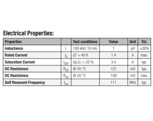
Figure 1: 74438313010 electrical characteristics
・Inductance: The inductance value of the inductor. 1μH±30% under test conditions.
It is necessary to consider that the value changes depending on conditions such as tolerance and current value.
・Rated Current: Rated current based on temperature rise. When 1.4A is applied, ⊿T=40℃typ.
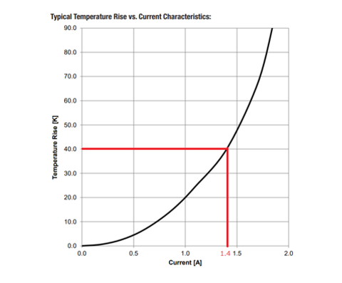
Figure 2: 74438313010 temperature rise curve
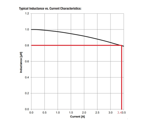
Figure 3: 74438313010 inductance DC superimposition characteristics
Figure 2 is the characteristic curve.
Since the loss is P=RI 2 [W], ⊿T when used at half the current is 10°C, which is 1/4 of the calculated value.
When operating with AC, AC loss must also be considered.
・Saturation Current: Rated current based on inductance change value. When 3.4A is applied, the inductance value decreases by about 20% from the initial value.
Figure 3 shows the characteristic curve.
If a current larger than this is applied, the inductance will drop further and approach magnetic saturation.
It can be said that a design with a margin for this value is desirable in order to avoid magnetic saturation.
・DC Resistance: The DC resistance value of the inductor. typ and max values @20℃.
Due to the temperature coefficient, this value increases during high temperature operation.
・Self Resonant Frequency: Value of self-resonant frequency
The operating frequency should be low enough for this value.
The self-resonant frequency will be explained in the equivalent circuit of the inductor in the next section.
Equivalent circuit of inductor
The equivalent circuit of an inductor is generally expressed as shown in Figure 4.
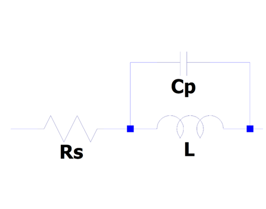
Figure 4: Equivalent circuit of an inductor
Rs is a DC resistance (hereafter referred to as DCR) component, which mainly causes voltage drop and heat generation. Cp is a stray capacitance component, which causes a self-resonance phenomenon and limits the frequency that can be used.
The self-resonant frequency (SRF) of an inductor can be calculated like this.
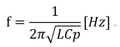
In the 74438313010 shown in the inductor characteristics, the SRF is 111MHz, so by substituting L=1[μH], this inductor Cp can be calculated to be about 2pF.
Figure 6 shows the results of LTspice simulation. It can be seen that the impedance reaches its maximum value at about 111 MHz, the resonance point, and decreases from there.
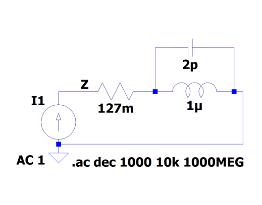
Figure 5: 74438313010 equivalent circuit
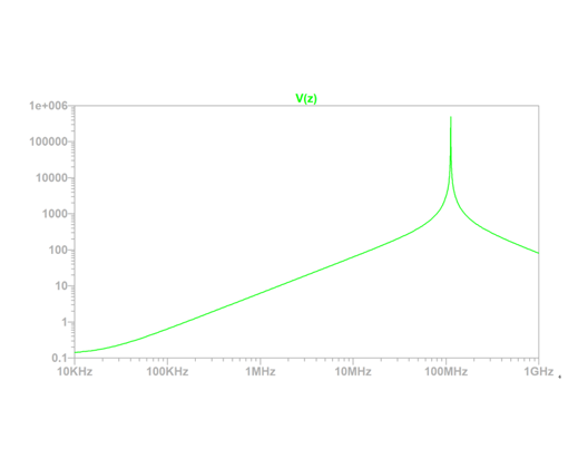
Figure 6: 74438313010 frequency response
For an ideal inductor, Cp=0, so the impedance increases as the frequency increases.
Please also refer to the related article “Basics of LC - Part 2 Inductor Operation”.
The contents are summarized below.
・The inductor has a DCR component and a stray capacitance component
・Impedance increases up to SRF and has inductive characteristics
・After SRF, the impedance decreases, becomes capacitive, and loses its function as an inductor.
circuit download
If you would like to purchase from Macnica-Mouser, please click here
Ulto Electronics products are available for purchase at Macnica-Mouser (Macnica-Mouser), a mail order site for semiconductors and electronic components.
If you want to buy a product in a hurry, you can consider Macnica-Mouser.
Inquiry
If you have any questions about this article, please contact us using the form below.
Würth Elektronik Manufacturer Information Top
If you would like to return to the Würth Electronics Manufacturer Information top page, please click below.