- Semiconductor BusinessHOME
- Products and Services of Macnica,Inc.
-
technical information

-
Events and Seminars
- Handling Manufacturer
- Support
- Inquiry
- Click here to purchase products
- Semiconductor business e-mail magazine registration
![]()
![]() Narrow down by specifying conditions
Narrow down by specifying conditions
現在2183件がヒットしています。check
Run your application with CapTIvate
So far, we have introduced the development procedure for a single MSP430FR2633 MCU with CapTIvate capacitive touch technology.
Click here for the development procedure article
Touch detection is possible even with water droplets! What are the two capacitive methods?
Set up your design environment in minutes with the CapTIvate Design Center GUI
The MSP430FR2633 microcontroller has basic functions such as an AD converter and timer, but in actual equipment, it may be used to connect to a host microcontroller with a display function such as an LCD panel.
Assuming such a use, this time, Texas Instruments provides an implementation example that transmits the touch sensing result of the touch sensor board (CAPTIVATE-PHONE) to a host microcomputer equipped with a serial interface (UART) and displays it on an LCD. I will introduce the reference design.
Hardware preparation
what to prepare
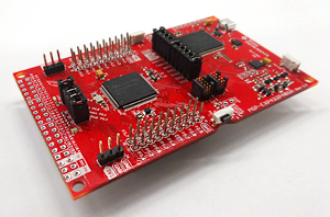
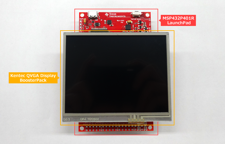
1. MSP432P401R LaunchPads
Low power, high performance MSP432 MCU evaluation kit
Employing a 32-bit ARM Cortex-M4F core and inheriting the features of the MSP430 microcontroller series, this is a high-performance, low-power MSP432 microcontroller evaluation board.
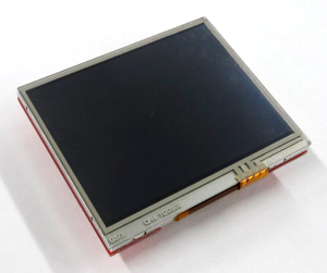
2. Kentec QVGA Display BoosterPack
A color TFT liquid crystal display board that can be connected to Launchpad.
- 3.5 inch QVGA (320x240 resolution)
- SPI interface
- 4-wire resistive touch screen
- White LED backlight
- LED backlight driver circuit
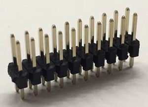
3. 2.54mm pin headers (10pin x 2 rows) x 2 for connection
*The pin header is not included with the evaluation board. It is necessary to purchase the items shown in the right figure separately.
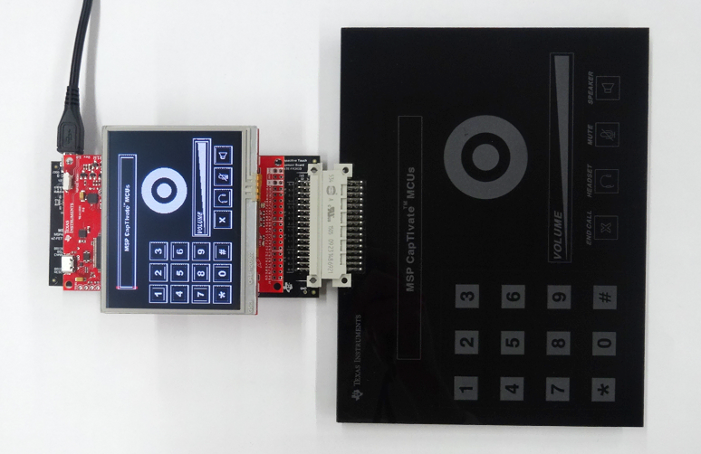
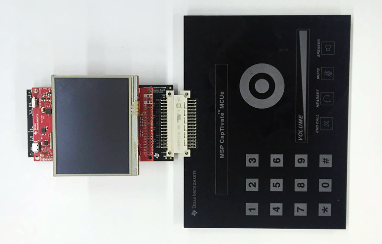
Assembling the evaluation board
- Mount the pin header for connection on the MSP430FR2633 board (CAPTIVATE-FR2633) included in the MSP CapTIvate MCU Development Kit.
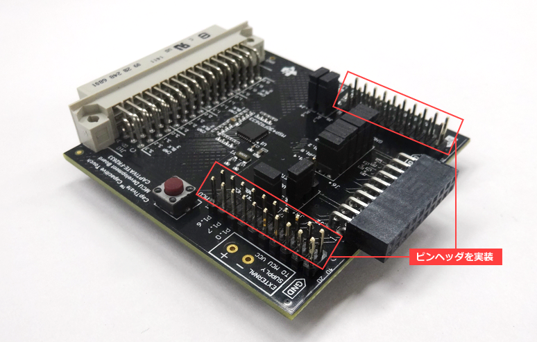
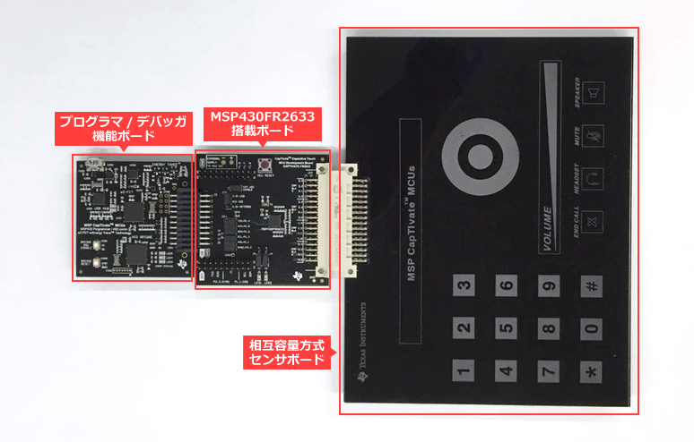
- Connect the mutual capacitance sensor board (CAPTIVATE-PHONE) and the programmer/debugger function board (CAPTIVATE-PGMR) to the MSP430FR2633 board (CAPTIVATE-FR2633).
- Connect Kentec QVGA Display BoosterPack to MSP432P401R LaunchPad.
- Connect the LCD board assembled in "Step 3" to CAPTIVATE-PHONE assembled in "Step 2".
Software preparation
Next, let's write the software to the assembled hardware.
Follow the steps below to download the program from the manufacturer's site and write it to the microcomputer.
software download
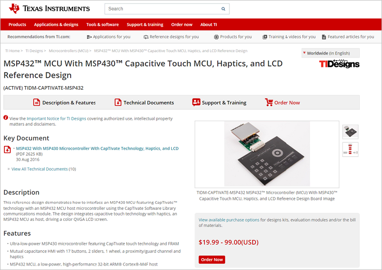
- Go to "MSP432™ Microcontroller (MCU) With MSP430™ Capacitive Touch MCU, Haptics, and LCD Reference Design" (http://www.ti.com/tool/TIDM-CAPTIVATE-MSP432/).
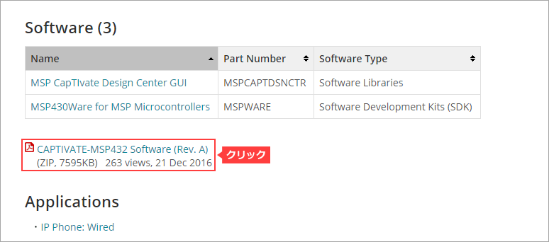
- Scroll down and click on the program (CAPTIVATE-MSP432 Software) to download.
(Please unzip the zip file after downloading)
Write the downloaded program to the microcomputer
- Start the integrated development environment (CCS).
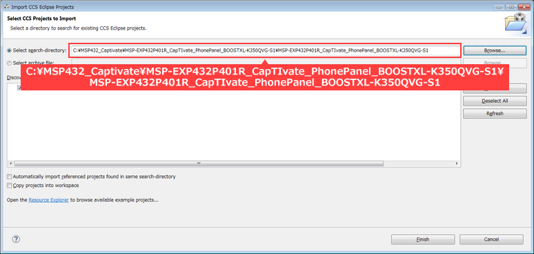
- Select Project → Import CCS from the menu bar.
- Next, click the Browse button, specify the folder where the downloaded program is stored, check the project to load (MSP-EXP432P401R_CapTIvate_PhonePanel_BOOSTXL-K350QVG-S1), and click Finish. (The figure below shows an example of unzipping the downloaded zip file directly under Disk-C.)
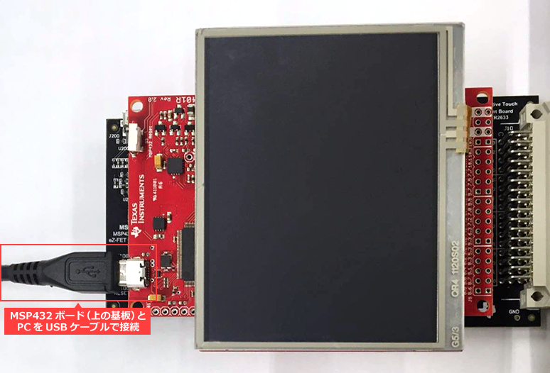
- Connect the MSP432 board (upper board) and the PC with a USB cable.
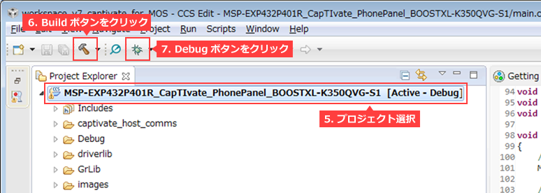
- Select a project.
- Click the hammer icon (Build). (Compilation is successful if you can see "BuildFinished" without any errors.)
- Click the insect icon (Debug) to write the program to the microcomputer.
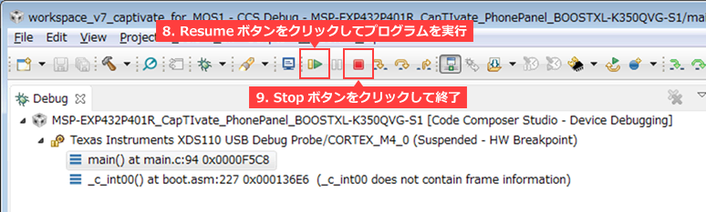
- Click the triangle icon (Resume) in the debug window to run the program.
- Click the red icon (Stop) to finish debugging.
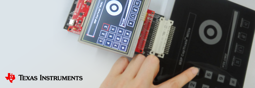
Check it works
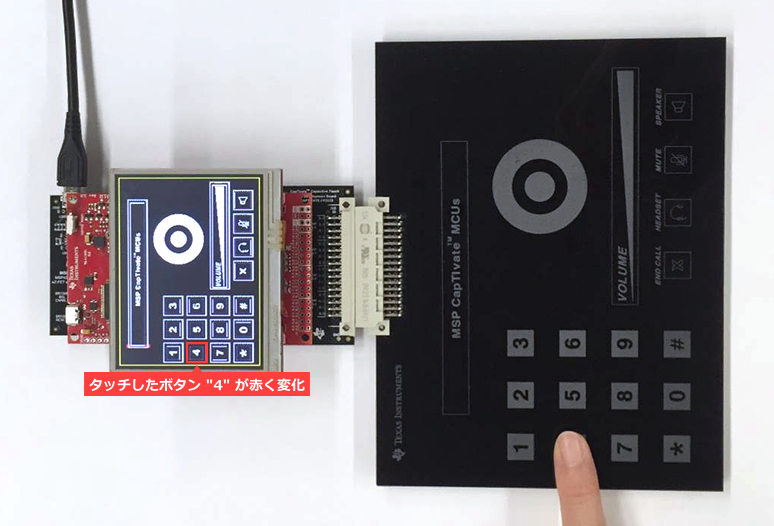
After reconnecting the USB cable connecting the PC from the MSP432 board (upper board) to the programmer/debugger function board (lower board), touch the touch sensor board and check the operation.
You should be able to observe that the icons corresponding to the buttons, sliders, and wheels on the touch sensor board change to red.
At the end
This time, we introduced an application that uses the reference design (TI-Design) provided by Texas Instruments to send CapTIvate's touch sensing results to another microcomputer (MSP432) and display them on an LCD.
Texas Instruments provides the following mechanisms to support application development, so please make use of them when considering products.
- Evaluation board, application board (Booster-pack)
- Reference design using Texas Instruments products (TI-Design)
Click here for recommended articles/materials
Capacitive touch sensing can be realized only with a microcomputer! What is CapTIvate Technology?
Set up your design environment in minutes with the CapTIvate Design Center GUI
Touch detection is possible even with water droplets! What are the two capacitive methods?
Ultra low power consumption with CapTIvate wake-on-touch
Easy tuning of CapTIvate touch sensitivity with GUI
Easy tuning with CapTIvate even if there is moisture Part 1
Easy tuning with CapTIvate even if there is water Part 2
CapTIvate: Quick Start Guide
What is a sensor? Basic knowledge for digitization and IoT
Click here to purchase products
MSP CapTIvate MCU Development Kit MSP-CAPT-FR2633
MSP432 Series MSP432P401R LaunchPad
Contact Us

