- Semiconductor BusinessHOME
- Products and Services of Macnica,Inc.
-
technical information

-
Events and Seminars
- Handling Manufacturer
- Support
- Inquiry
- Click here to purchase products
- Semiconductor business e-mail magazine registration
![]()
![]() Narrow down by specifying conditions
Narrow down by specifying conditions
現在2189件がヒットしています。check
Introduction
This time, sensing is performed with ONSEMI's RSL10.
Here, we will guide those who are developing the RSL10 for the first time and those who will be developing it for the first time on how to perform sensing with the RSL10.
This article consists of two parts, the first part and the second part.
In the first installment of the last time, I flashed the L with the RSL10. Also, please refer to this article for details on preparing the development environment.
Bluetooth®5 certified SoC, RSL10 first time evaluation record of all 3 times -1st "Turn on the LED"
Things to prepare, development tools, and preparation of the development environment
what to prepare
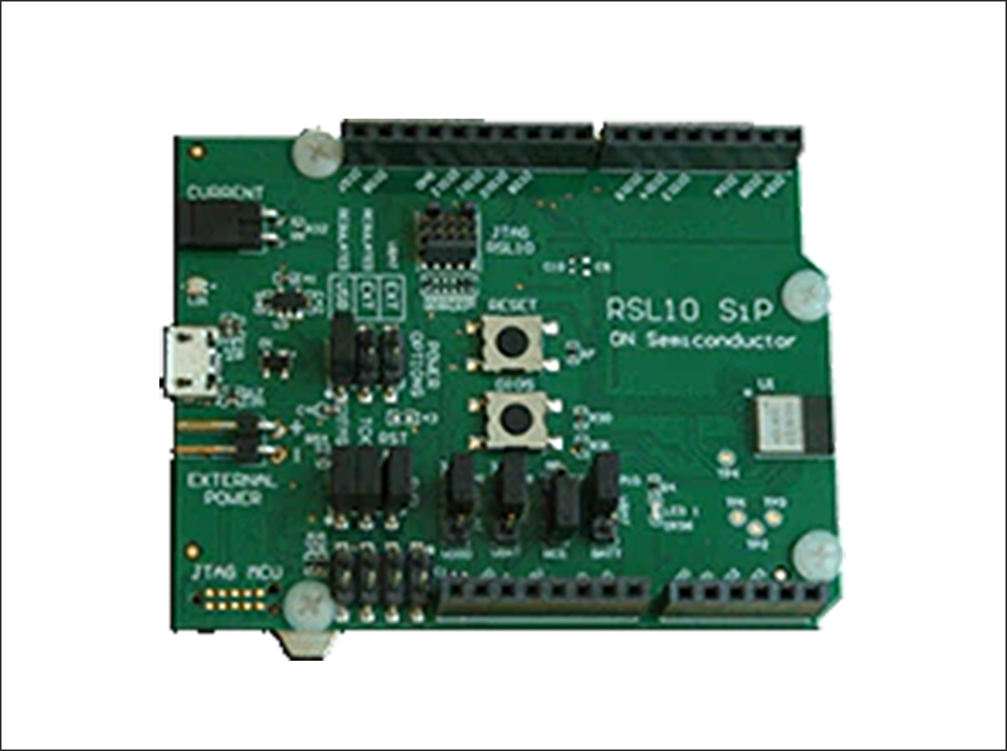
RSL10-SIP-001GEVB
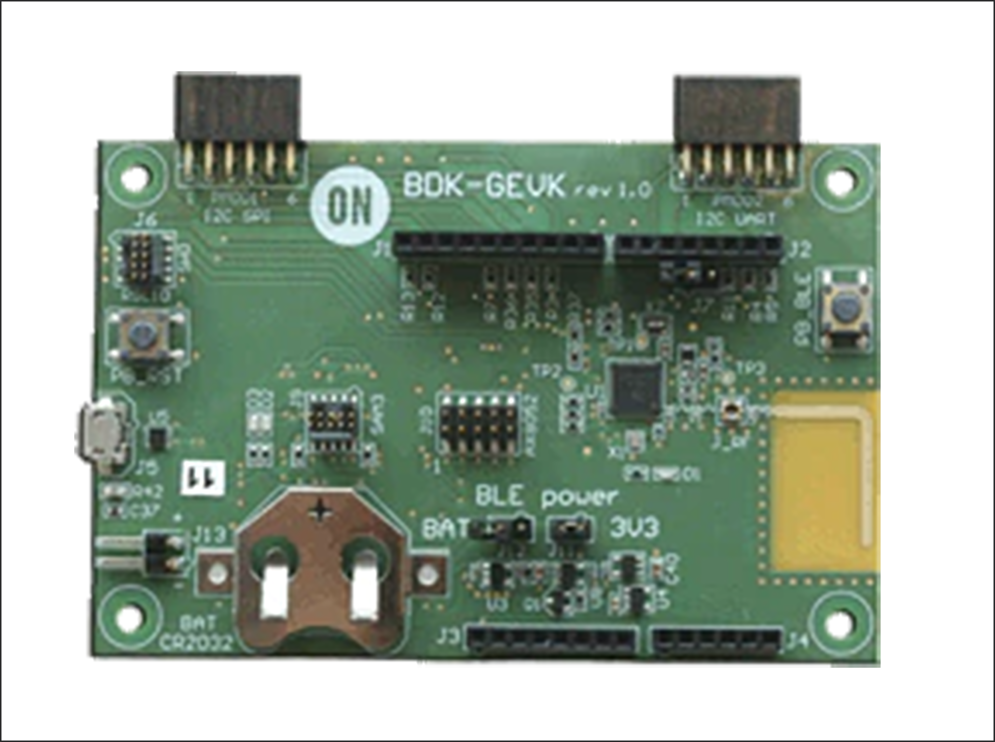
RSL10-BDK-GEVK
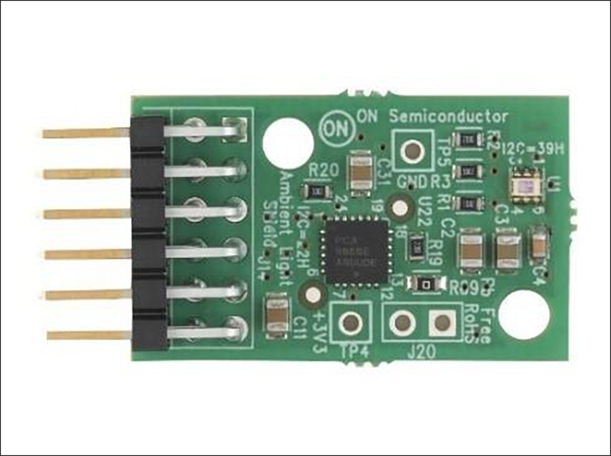
NOA-1305
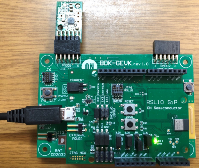
Hardware connection method
Connect as shown below.
RSL10-SIP-001GEVB is a product in which the RSL10, antenna (*), and other peripheral passive components are packaged in one package, so please connect as shown below.
(*) Certified to international radio regulations (CE, IC, KC, MIC, FCC)
development tools
・onsemi IDE: An Eclipse®-based integrated development environment.
Preparing the development environment
For the preparation of the development environment, please refer to the first article in the previous article.
Start designing with onsemi IDE
Importing the sensing sample code
1. Start ONSEMI's IDE. To open the ON Semiconductor IDE, select ON Semiconductor > ON from the Windows Start menu.
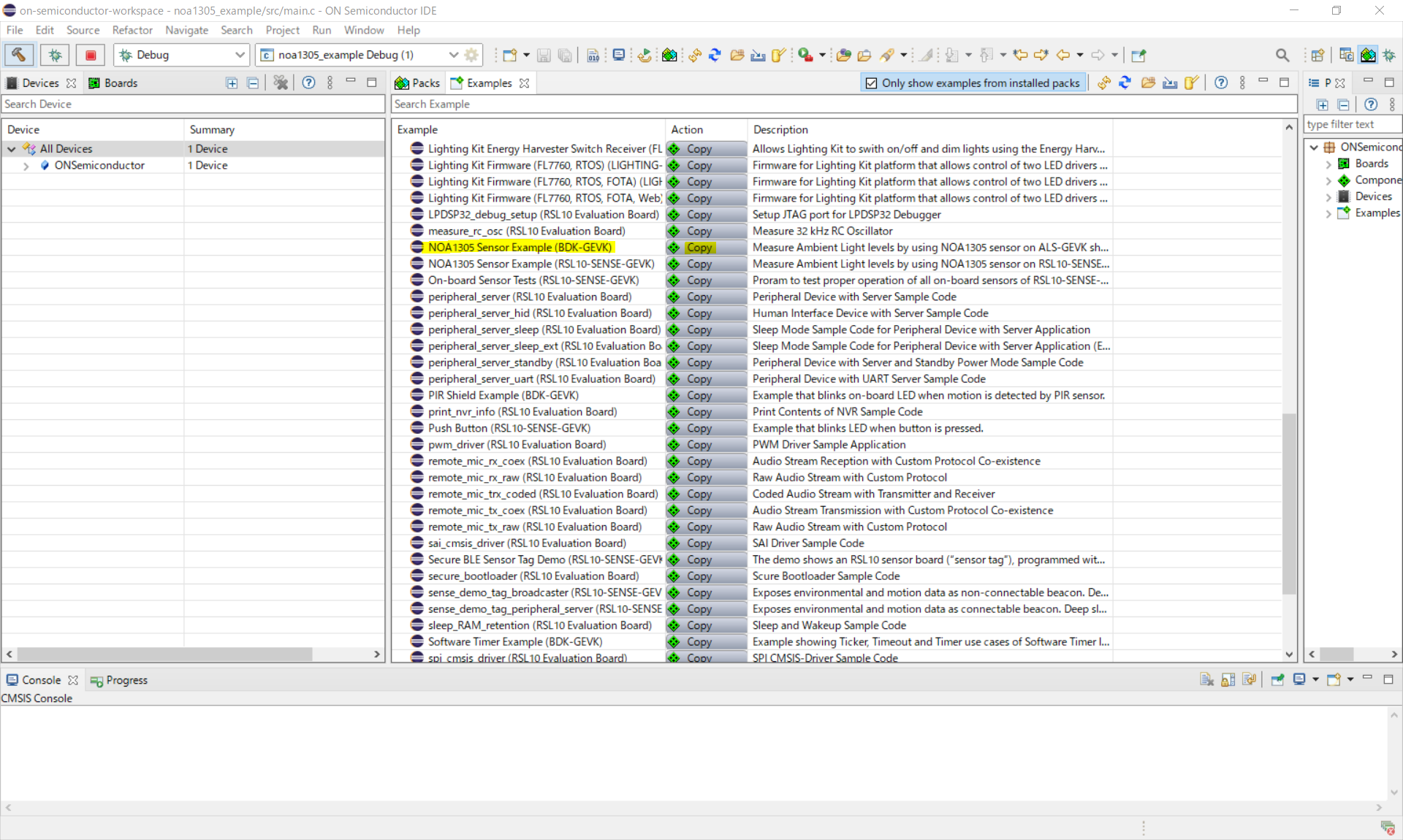
2. Click on the "Example" tab to see a list of all example projects included in the RSL10 CMSIS-Pack.
3. Select the example project NOA1305 Sensor Example(BDK-GEVK) and click the copy button to import it into your workspace. (See Fig. 1)
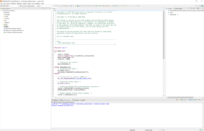
4. C/C++ will open in Project Explorer and you will see the newly copied project (NOA1305).
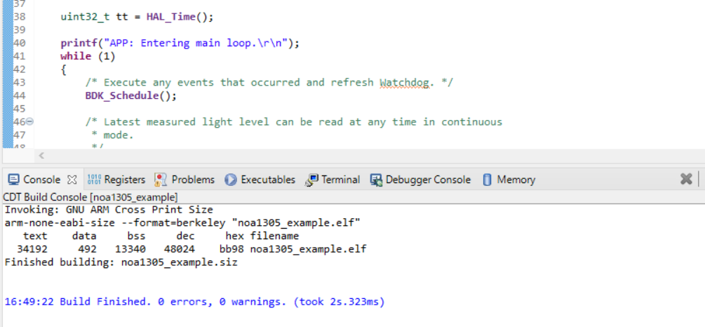
5. By clicking main.c in the NOA1305_example folder on the Project Explorer, you can check the C language code related to sensing. (See Figure 2)
How to build the sensing sample code
1. Right-click the folder for NOA1305_example and click Build Project. Alternatively, select a project and click [Build Project].
2. When the build is executed, the output of the build will be displayed on the on-semi IDE C/C++ as shown in Figure 3.
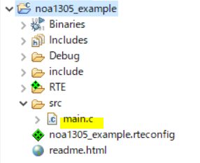
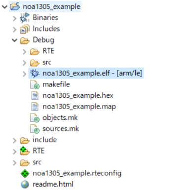
3. The main results output to the Debug folder on the Project Explorer are as follows. Shown in Figure 4.
The file used for sensing is noa1305_example.elf.
How to debug the sensing sample code
Debug using the noa1305_example.elf file.
1. Right-click the noa1305_example.elf file in the Project Explorer and select Debug As > Debug Configurations.
2. When the Debug Configurations dialog appears, right-click GDB SEGGER J-Link Debugging and select New Configuration.
You will see a new configuration of noa1305_example.elf under the GDB SEGGER heading.
The details of the new configuration appear in the right panel.
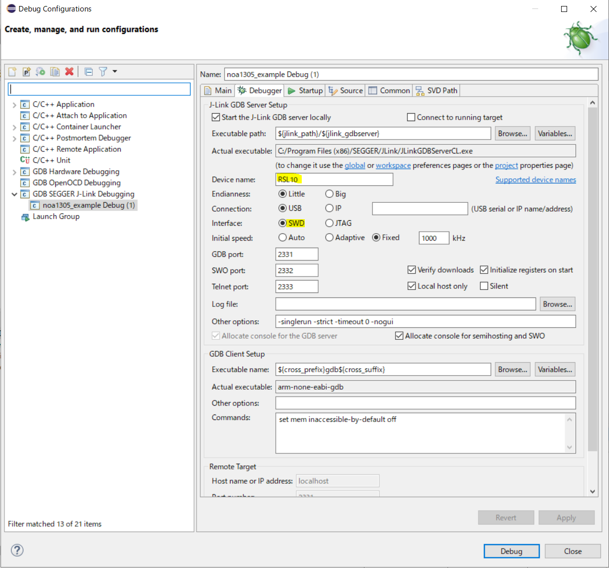
3. Go to the Debugger tab and enter "RSL10" in the "Device Name" field.
Make sure SWD is selected as the target interface. (See Fig. 5)
4. After the configuration update is complete, connect the evaluation and development board to your PC with a micro USB cable and click Debug.
J-Link will automatically download the noa1305_example example code and store it in the RSL10 's flash memory.
5. After clicking Debug, click Resume (F8) in Figure 6 below.

6. After clicking Resume, click Open a terminal in Figure 7 below.

7. When I click Open a terminal, I get an error message like Figure 8.
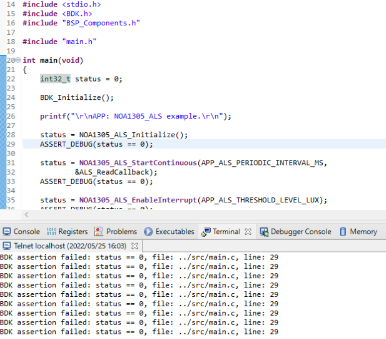
That's it for the first part.
In the second part, I will explain the flow of identifying the cause of this error and how to actually perform sensing with the RSL10.
Inquiry
If you are interested in the contents and products introduced this time, please contact us.
Onsemi Manufacturer information Top
If you want to go back to ONSEMI Manufacturer Information Top, please click below.