- Semiconductor BusinessHOME
- Products and Services of Macnica,Inc.
-
technical information

-
Events and Seminars
- Handling Manufacturer
- Support
- Inquiry
- Click here to purchase products
- Semiconductor business e-mail magazine registration
![]()
![]() Narrow down by specifying conditions
Narrow down by specifying conditions
現在2183件がヒットしています。check

Introduction
This time, we will use ONSEMI's RSL10 to light up the LED (hereinafter referred to as "L blinking"). Turn on LED1 (DIO6) on the RSL10 evaluation/development board.
In this article, we will guide those who are evaluating RSL10 for the first time and how to make the LED blink for those who will be developing from now on.
For product introduction of RSL10, please refer to this article.
Things to prepare and development tools
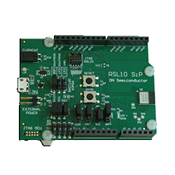
・RSL10-SIP-001GEVB: RSL10 evaluation board
・onsemi IDE: An Eclipse®-based integrated development environment.
Preparing the development environment
1. Go to the RSL10 product page. Link to product page here
2. Use the download button on the main page.
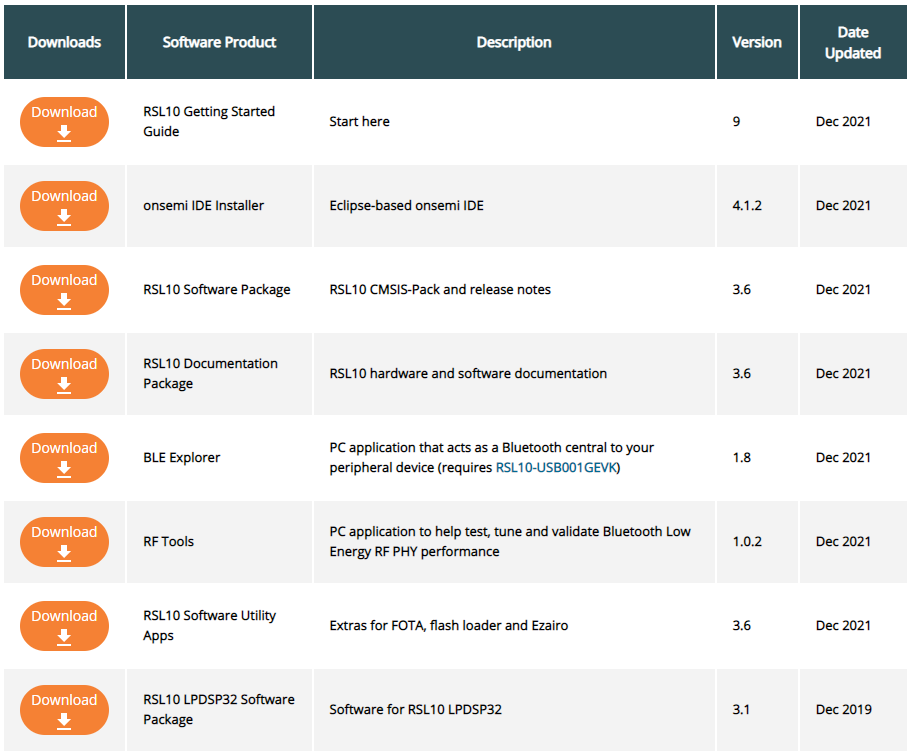
3. Download the RSL10 Started Guide and read the detailed instructions.
4. Download and install the Eclipse-based on-semi IDE installer.
5. Download and unzip the RSL10 Software Package containing the RSL10 CMSIS Pack.
6. Follow the instructions in the RSL10 Started Guide to install the CMSIS pack.
Here are the steps:
RSL10 CMSIS pack installation instructions
1. It is important to create a new workspace for each new version of the IDE to ensure compatibility.
Create a new workspace using either Windows Explorer or the ON Semiconductor Launcher in step 2.
Example) c:\workspace
2. Open the Windows Start menu and select ON Semiconductor > ON Semiconductor IDE.
From the ON Semiconductor IDE Launcher screen, browse to your new workspace. Select and click [Launch].
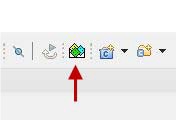
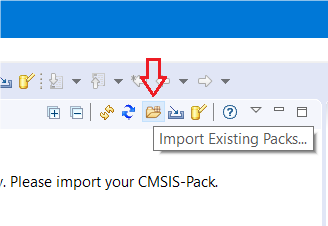
3. At the top of the Workbench perspective, click to open the "Make the CMSIS Packs Manager Perspective visible" icon. (See Figure 1 below)
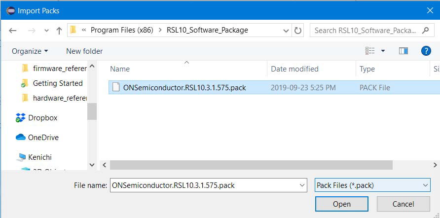
4. Click on the “Import Existing Packs” icon and select the pack file ONSemiconductor.RSL10.<version>.pack.
where <version> is a number like 3.1.575.
Select it and click Open (see Figure 2 below)
5. The IDE prompts the user to read and accept the license agreement and installs RSL10 CMSIS-Pack to the specified root folder.
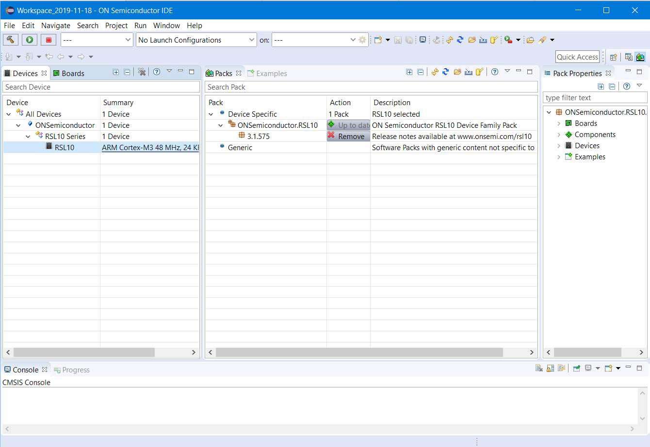
6. You should now see RSL10 CMSIS-Pack in the list of installed packs.
Under the Devices tab, expand All Devices > ONSemiconductor > RSL10 Series and you will see a list of RSL10s there.
Installed packs can be managed in the Packs tab.
Expanding ONSemiconductor > RSL10 reveals the Pack Properties tab.
Figure 3 below shows how the Pack Manager Perspective looks after installation.
Start designing with onsemi IDE
Importing the LED blinking sample code
1. Start ONSEMI's IDE.
To open the ON Semiconductor IDE, select ON Semiconductor > ON from the Windows Start menu.
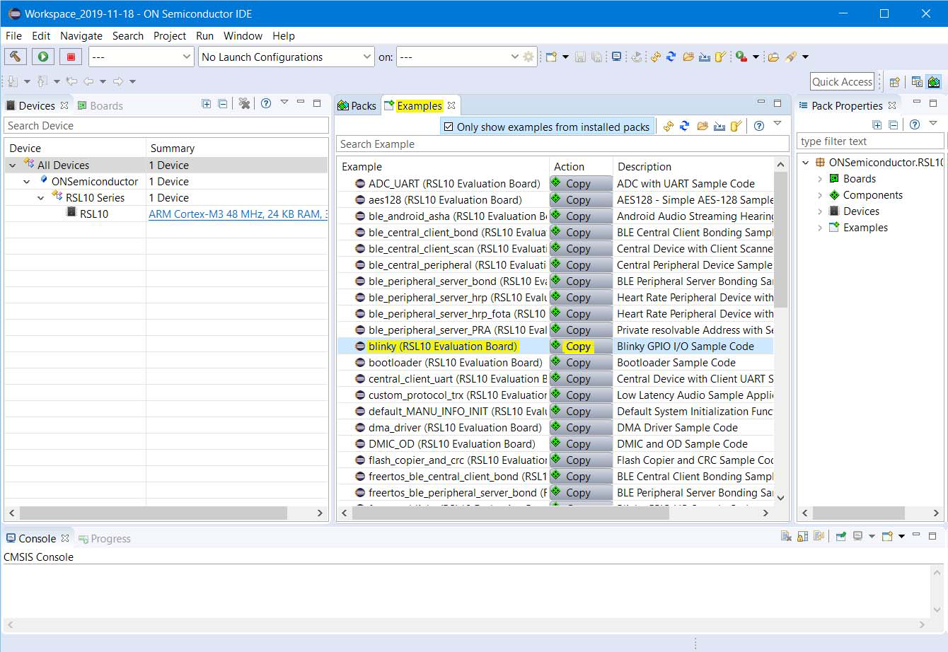
2. Click on the "Example" tab to see a list of all example projects included in the RSL10 CMSIS-Pack.
3. Select the sample project called blinky and click the copy button to import it into your workspace. (See Figure 4 below)
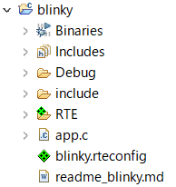
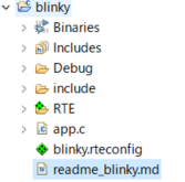
4. C/C++ will open in Project Explorer and you will see the newly copied project (blinky).
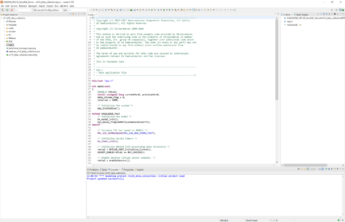
5. By clicking app.c in the blinky folder on the Project Explorer, you can check the C language code for the blinking lights. (See Figure 5 below)
How to build the LED blinking sample code
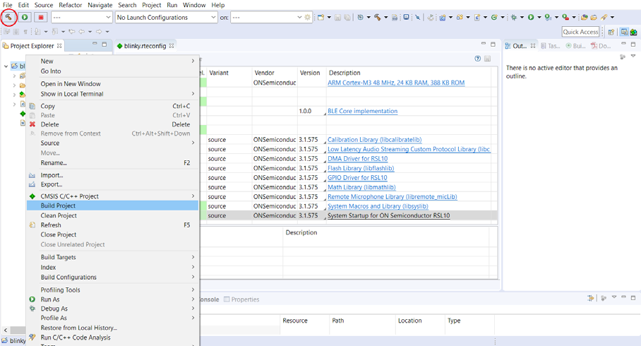
1. Right click the folder for blinky and click Build Project. Alternatively, select a project and click [Build Project].
Or display the hammer-like icon, Build Project, as shown in Figure 6.
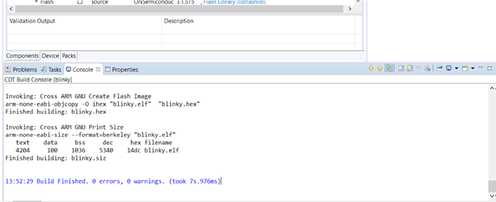
2. Once the build is executed, the output of the build will be displayed on the on-semi IDE C/C++ as shown in Figure 7.
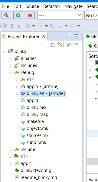
3. The main results output to the Debug folder on the Project Explorer are as follows. Shown in Figure 8.
The file used for blinking is blinky.elf.
- blinky.hex: HEX file to load into flash memory
-blinky.elf: ARM® executable, run from RAM, used for debugging
- blinky.map: map file of sections and memory usage
How to debug the LED blinking sample code
Debug using the blinky.elf file.
1. Right-click the blinky.elf file in the Project Explorer and select Debug As > Debug Configurations.
2. When the Debug Configurations dialog appears, right-click GDB SEGGER J-Link Debugging and select New Configuration.
You will see a new configuration for blinky under the GDB SEGGER heading.
The details of the new configuration appear in the right panel.
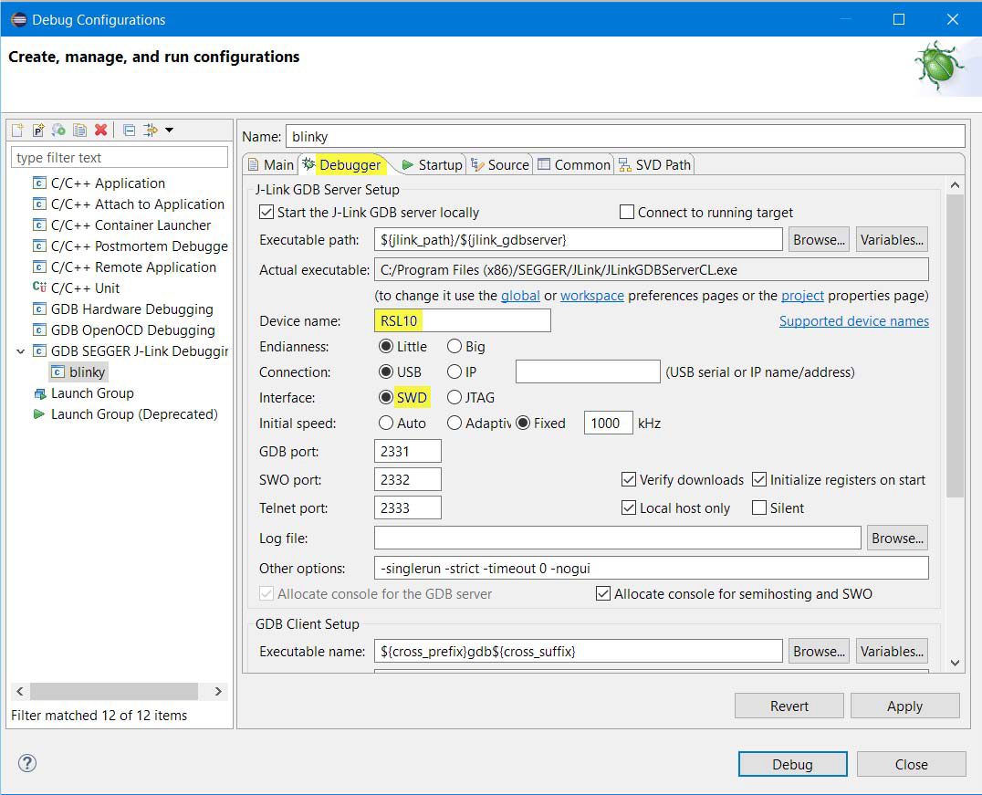
3. Go to the Debugger tab and enter "RSL10" in the "Device Name" field. Make sure SWD is selected as the target interface. (See Figure 9 below)
4. After the configuration update is complete, connect the evaluation and development board to your PC with a micro USB cable and click Debug.
J-Link automatically downloads a sample code called blinky and stores it in the RSL10 's flash memory.
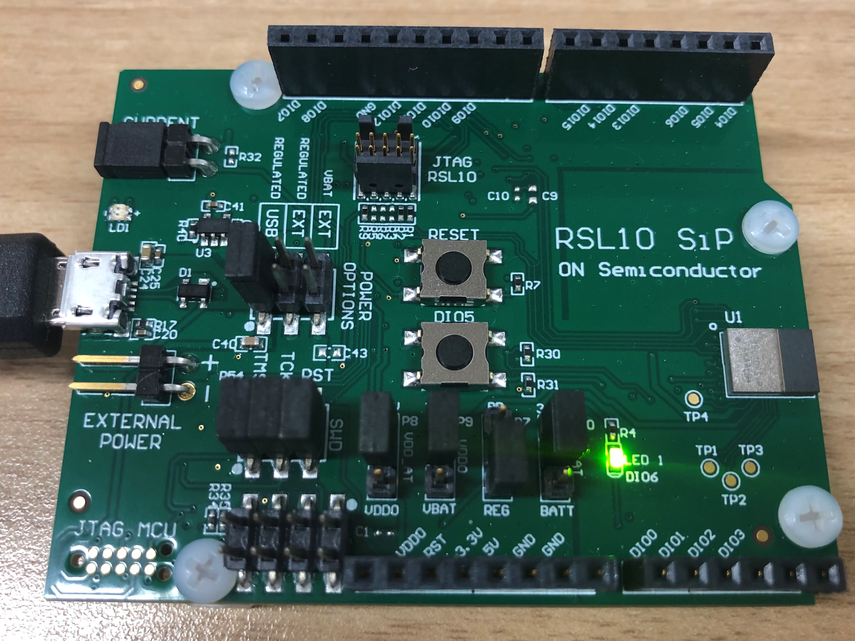
5. I was able to confirm the L blinking. (See Figure 10 below)
How to change the lighting time of the L flashing
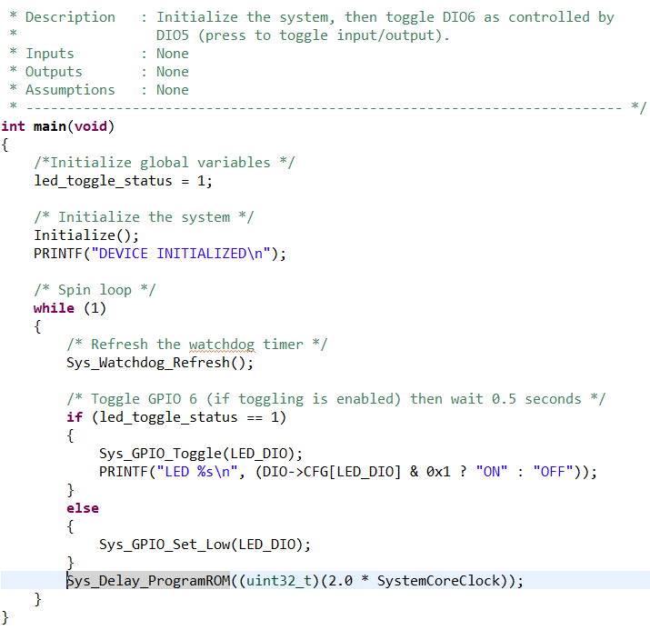
1. If you check the contents of the app.c file, you can see led_toggle_status (LED lighting status) and Sys_Delay_Program ROM (description about time). (See Figure 11 below)
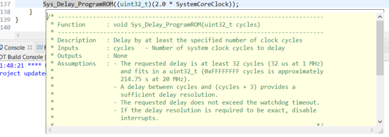
2. Press F2 at Sys_Delay_Program ROM to see what code you are writing. (See Figure 12 below)
There is a description in the description that it delays at least the specified number of clock cycles.
3. On line 137 in the code of App.c,
Sys_Delay_ProgramROM((uint32_t)(2.0 * SystemCoreClock));
You can change the lighting time by changing the number before SystemCoreClock.
When you have a problem with blinking L using RSL10
Blinkyin the file Readme_blinky.md Please click to check the contents. (under
Readme_blinky.mdThe contents of are shown below.
Overview
1. Use DIO6 as a toggle output signal. This DIO6 is selected to blink an LED on the evaluation and development board.
2. Use DIO5 as an input signal to disable and re-enable DIO6 toggling.
This DIO selection was chosen so that the toggle state of DIO6 can be changed using a pushbutton input switch connected to the DIO connection on the evaluation and development board.
The source code is in `app.c` and no header files are defined.
Hardware requirements
This application can be run on the RSL10 evaluation and development board.
This application requires no external connections and can be run on the RSL10 Evaluation Development Board.
Import project
For information on how to import the sample code into the IDE's workspace, refer to Importing the LED Flashing Sample Code in Start Designing with Onsemi IDE in this article.
inspection
To confirm that the application is working properly, continuously blink DIO6 on the evaluation development board.
remarks
The RSL10's firmware may not successfully re-flash due to application sleep mode or persistent resets. (due to design or programming error)
To avoid this scenario, a software recovery mode using DIO12 can be implemented. Here are the steps:
1. Connect DIO12 to ground.
2. Press the RESET button (applications paused at the start of the initialization routine will restart).
3. Reflash the RSL10. After a successful reflash, disconnect DIO12 from ground and press the RESET button. Then the application works fine.
At the end
This time, I used ONSEMI's RSL10 to flash the lights. Next time (Part 2), I would like to use RSL10 for sensing.
Inquiries
If you are interested in the contents and products introduced this time, please contact us.
Onsemi Manufacturer information Top
If you want to go back to ONSEMI Manufacturer Information Top, please click below.