- 半導体事業HOME
- マクニカの製品・サービス
-
技術情報

-
イベント・セミナー
- 取扱メーカー
- サポート
- お問い合わせ
- 製品購入はこちら
- 半導体事業のメルマガ登録
![]()
![]() 条件を指定して絞り込む
条件を指定して絞り込む
現在2186件がヒットしています。check

Low Pass Filter
Low Pass Filterには、位相比較器の出力を平滑化する役割とJitterを圧縮する役割があります。Filterの時定数はPLLが安定するまでに掛かる時間に影響を与えます。これは、時定数がFilterの応答特性を決定するためです。時定数を含むPLLの指標の一つにダンピングファクターがあります。通常のPLLでは、√2/2程度の値にダンピングファクターを設定するように設計されます。安定時間が長くてもPLLの同期を外れにくくするときにはダンピングファクターを大きく取ることもあります。
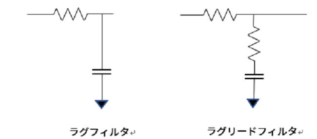
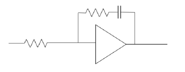
ラグフィルターは位相遅れに対して位相は戻りませんが、ラグリードフィルターは位相進み/遅れをおこなうことができ、位相余裕を持つことができます。ただし、高域での減衰を得ることができないため、2次または3次のフィルタを構成することになります。通常、ラグリードフィルターの後段にラグフィルターを構成して高域での減衰を補ったりします。広帯域のPLLを設計する場合は上記のようなパッシブフィルターでゲインが不足するようであれば、オペアンプを使用して交流ゲインを稼ぐこともできます。
Filterにゲインを持たせることで、FilterによるJitterの圧縮にも影響を及ぼします。Filterのカットオフ周波数は、位相比較周波数とReference Clockに重畳されたJitter周波数を考慮して決めなくてはなりません。高次Filterを用いることで、高域でのJitterの圧縮効果を上げる必要があります。
次回は、分周回路について記載します。
お問い合わせ
本記事についてのお問い合わせ、ご質問は、以下のボタンからお願いします。
Microchip メーカー情報Topへ
Microchip メーカー情報Topページへ戻りたい方は、以下をクリックください。