- Semiconductor BusinessHOME
- Products and Services of Macnica,Inc.
-
technical information

-
Events and Seminars
- Handling Manufacturer
- Support
- Inquiry
- Click here to purchase products
- Semiconductor business e-mail magazine registration
![]()
![]() Narrow down by specifying conditions
Narrow down by specifying conditions
現在2191件がヒットしています。check

Integer Divider
Integer dividers require integer division, meaning that the VCO's output frequency is an integer multiple of the PLL's Reference input. For example, if the input Reference Clock input is 10MHz and the VCO output is 100MHz, the 1/N divider should be divided by 10.
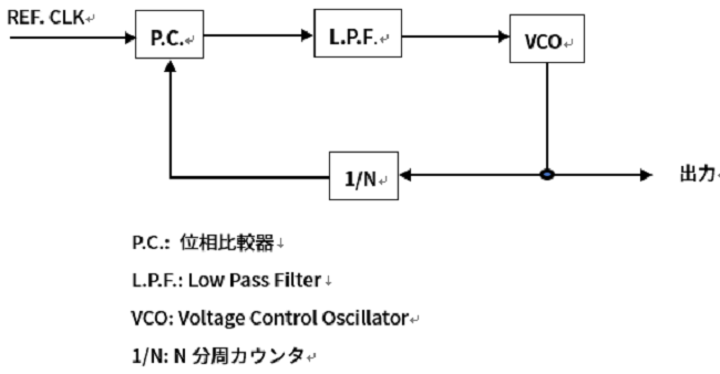
Fractional divider circuit
Fractional dividers are used when the VCO's output is not divisible by the PLL's Reference Clock input. As a simple example, consider a reference clock input of 21MHz and a VCO output of 100MHz. The greatest common divisor is 1MHz, and the PLL can be configured even with integer division. Consider the case where you want to operate the PLL using the direct Reference Clock input to increase the closed-loop gain of the PLL. In this case, the 1/N divider circuit cannot divide by an integer and needs to divide by a decimal point. It is possible to generate 21MHz from 100MHz by combining four divide-by-fives and one divide-by-four. However, considering the ease of making the circuit, if one divides by 4 after dividing by 5 four times, fractional spurious will occur. If you divide by 5 4 times and divide by 4 once, a short pulse width cycle occurs in 5 clock cycles of 21MHz, and it is the same as 4.2MHz (1/5 of 21MHz) being superimposed as Jitter. increase.
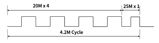
Fractional Spurious is dispersed by inserting the frequency division by 4 randomly, not periodically, and becomes the same as Spread Spectrum Clock. Also, Jitter is reduced to some extent by setting the LPF Cut Off to a frequency that suppresses the superimposed Jitter. it can be suppressed.
Next time, I will write about Jitter and Wander.
Inquiry
If you have any questions regarding this article, please use the button below.
To Microchip manufacturer information Top
If you want to return to Microchip manufacturer information top page, please click below.