- Semiconductor BusinessHOME
- Products and Services of Macnica,Inc.
-
technical information

-
Events and Seminars
- Handling Manufacturer
- Support
- Inquiry
- Click here to purchase products
- Semiconductor business e-mail magazine registration
![]()
![]() Narrow down by specifying conditions
Narrow down by specifying conditions
現在2171件がヒットしています。check

In recent years, ICs with PLL functions have become popular, and it seems that the discrete PLL itself is no longer used. PLL ICs are becoming more multi-functional, and control settings are becoming more complex. If you understand what each IC setting means by having basic knowledge of PLL, it will be easier to deal with problems when they occur. Therefore, in this article, we will introduce the basic configuration of an analog PLL.
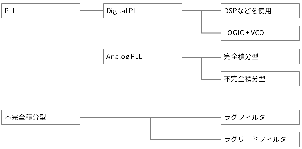
Types of PLLs
PLLs are broadly classified into Digital PLLs and Analog PLLs, which control the output frequency with a DSP or the like. Analog PLL is classified into 3 types according to the configuration of Filter. I think that many recent PLL ICs are digital PLL only or a combination of digital PLL and analog PLL.
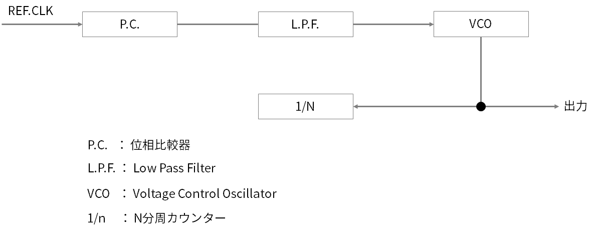
Basic configuration of PLL
A typical analog PLL consists of a phase comparator, low pass filter, voltage control OSC, and 1/N divider as shown in Figure 2. A phase comparator is sometimes described as a frequency phase comparator.
The reference clock input to the phase comparator compares the phase with the output clock of the PLL, smoothes the comparison result with a low pass filter, and inputs it to the voltage control terminal of the VCO to adjust the oscillation frequency.
Next time, I will describe the operation of the phase comparator.
Inquiry
If you have any questions regarding this article, please contact us below.
To Microchip manufacturer information Top
If you want to return to Microchip manufacturer information top page, please click below.