- Semiconductor BusinessHOME
- Products and Services of Macnica,Inc.
-
technical information

-
Events and Seminars
- Handling Manufacturer
- Support
- Inquiry
- Click here to purchase products
- Semiconductor business e-mail magazine registration
![]()
![]() Narrow down by specifying conditions
Narrow down by specifying conditions
現在2168件がヒットしています。check

hello! I'm Ryosu, a new engineer on the Lattice team.
Up to the last time, we created an SPI communication module.
After creating an SPI communication module, I feel relieved.
I got a new theme, "Next time, try making something using the NX, NEXUS series devices!"
Again, I thought, but when I think about it, I don't think I can explain how to use the Nexus series FPGA, how to use design tools, etc. to other people.
For study purposes, I would like to make a module using the new series of FPGA evaluation boards this time!
For those of you who are visiting this blog for the first time, let me give you a brief overview of this blog.
In this blog, I will introduce the process of making a temperature sensor, 7-segment LED, and Silicon Labs' BGX controlled by FPGA.
(If you're interested, I'll attach links to other episodes below, so please take a look!)
From concept decision to specification function decision and block diagram
concept
In the previous development, we created a module that displays the data acquired from the temperature sensor on a 7-segment LED.
Since it is a module that I worked hard to create, I decided to update the function of this module.
However, when I was worried about how to update the function, Mr. K, a senior
He gave me the advice, "Since we're dealing with other products in other departments, why don't we talk about something we can use?"
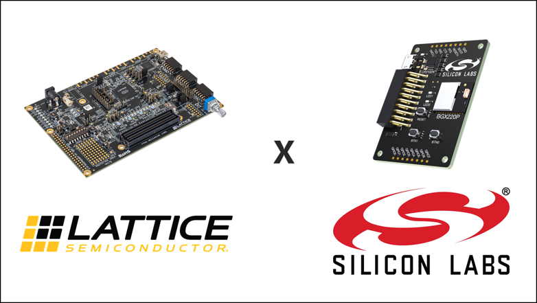
When I consulted Mr. H, a senior who handles Silicon Labs products,
I was told that a device called "BGX" that can easily communicate with a smartphone via Bluetooth would be good.
BGX is a device that performs Bluetooth communication with smartphones and UART communication with devices.
This time, using NEXUS FPGA and BGX, the output data from the temperature sensor
I would like to make a 7-segment LED display and a module that can be displayed on a smartphone!
Since the product will be updated from the last time, I would like to update the name as well.
I decided to call it "Indoor Temperature Monitoring-Ty EX".
Ty is a form of American slangthat takes the initials T and Y from"Thank you".
(It also contains Ryosu's desire to be a person who never forgets to be grateful...)
Just like last time, the concept was decided, and I was filled with motivation.
Function and specification
Last time, the temperature display method was a 7-segment LED display. (If you want to check the previous specification, click here)
In addition, this time I would like to add a function that allows communication with smartphones via BGX's Bluetooth communication.
From the smartphone side, (1) communication start/end and (2) changing the temperature reading method (mode change) are included as detailed functions.
The features and specifications are shown in the table below.
| function | specification | |
| Temperature display (displayed on smartphone) | command B | Start communication (Ready displayed on smartphone) |
| Command-F | End of communication (Stop displaying on smartphone) | |
| コマンド T | Temperature display Displayed on the smartphone only once | |
| Command A | Warning when temperature is 38°C or higher (symbol displayed on smartphone) | |
| Command-C | Continuous temperature display on smartphone | |
Inheriting the functional specifications from the last time, this time we have added a new command control function.
Since FPGA is UART communication, how to design RTL seems to be a point!
Design configuration diagram
It will be a configuration in which BGX is added to the configuration made last time.
Connect BGX to 3.3V I/O (High performance I/O) of FPGA, BGX and smartphone will be connected via Bluetooth.
A simple configuration diagram is shown below.
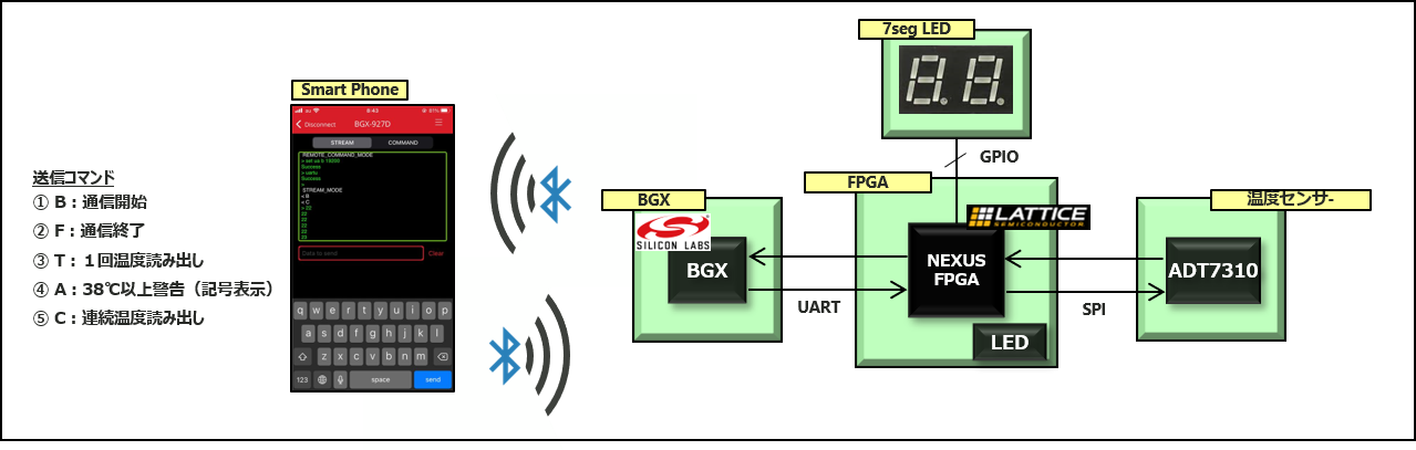
As you can see from the configuration, it seems that it is not necessary to create a substrate in particular.
The 7-segment LED display and temperature sensor board will be reused.
This time, we decided on the concept and functional specifications, and examined the configuration.
As an impression,
I have already experienced it once, and I was able to consider it smoothly because there are many diversions!
However, how to use FPGA and BGX, and UART communication are likely to be issues in the future. . .
Next time, I would like to check how to use the evaluation board and tools. See ya!
About the Lattice FPGA Getting Started Blog
Throughout the article, we are making a module that converts the temperature (SPI communication) acquired by the temperature sensor inside the FPGA and displays it on the 7-segment LED display!
If you are interested in "What is this newcomer making?"
I would be happy if you could check the module production process and the whole picture from the page below!
Related information