- Semiconductor BusinessHOME
- Products and Services of Macnica,Inc.
-
technical information

-
Events and Seminars
- Handling Manufacturer
- Support
- Inquiry
- Click here to purchase products
- Semiconductor business e-mail magazine registration
![]()
![]() Narrow down by specifying conditions
Narrow down by specifying conditions
現在2004件がヒットしています。check

Introduction
Nice to meet you, I'm Ryosu, a new member of the Lattice team!
From now on, I'm going to divide it into several parts, and I'm going to talk about a certain development from specification consideration to completion.
What is a certain development? you might think
Mr. F, a senior, asked me something like, "Can you play around with FPGA?"
I came up with the idea of using FPGA to move something for studying FPGA.
What I made will be a temperature sensor and a 7-segment LED controlled by FPGA.
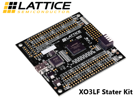
The FPGA to be used is a device called XO3LF on Lattice's XO3LF Starter Kit evaluation board.
I would like to be able to tell you what kind of specifications, block diagrams, RTL design, debugging, etc. along with "embarrassing failure stories".
Who are the people you recommend reading this blog? I think.
・People who use Lattice FPGA, design tool Diamond for the first time, or who are considering it
・People who want to use RTL (Verilog) for SPI communication and LED blinking
From the next time onwards, we will be updating all 9 parts with useful information such as "How to use Lattice tools" and "RTL coding for SPI communication", so please read them!
From concept decision to specification function decision and block diagram
Development process
Shortly after I joined the company, I had a conversation with senior Mr. F.
Ryosu: "FPGA has a lot of depth. I touched it a little at university, but it has a higher degree of freedom than I imagined."
Senior F-san: "Well, there are some difficult parts because of that degree of freedom, but if you can master the use of FPGA, you can do anything."
Ryosu "Will you be able to use FPGA?"
Senior F-san: "Well then, study and develop something using FPGA! Sounds like fun!"
Ryosu "It's also good for studying! I'll do it!"
From a little opportunity, I decided to develop using FPGA.
concept decision
I decided to decide from the concept right away, thinking that it would be nice if I could solve some problems.
It's summer time, so it's hot and I can't concentrate.
Even if I wondered, "What is the temperature right now?", I didn't have a thermometer to check.
Then I suddenly thought, "I would be happy if I could check the temperature in the room."
I thought that I could see the temperature and turn the air conditioner on or off depending on the temperature, but as a first step, I decided to create something that could measure the temperature and display it on something.
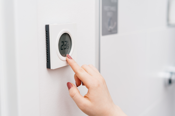
Therefore, the concept of this time is a product that allows you to check the temperature at a moment's notice.
I decided to call it "Indoor temperature monitoring-Ty".
Ty is a form of American slang that takes the initials T and Y from "Thank you".
It also contains Ryosu's desire to be a person who never forgets to be grateful. . .
Once the concept was decided, Ryosu was filled with motivation.
Function and specification
Once the concept is decided, the next step is to decide on the functions and specifications.
The function shall acquire the temperature from the temperature sensor and display the information on the 7-segment LED.
As for the specifications, when the temperature is between 15°C and 38°C, the temperature obtained at 500ms intervals is displayed in 7 segments, and when the temperature is less than 15°C or 38°C or more, all 7 segment LEDs are turned on for warning. .
In our daily life, we don't often check the temperature closely, so we made it communicate with the temperature sensor every 500ms. Also, when I looked into the temperature range, it seems that the temperature range for comfortable indoors in the summer is 25 to 28 degrees Celsius. decided.
Summarizing in the table is as follows.
Table 1. Features and specifications list
| function | specification | |
| temperature display |
Displayed on 7-segment LED |
Displays the temperature when the temperature is 15°C or higher and less than 38°C |
|
All LEDs light up (warning) when the temperature is less than 15°C or more than 38°C |
||
The functions and specifications have also been decided, and I am excited!
Component selection and block diagram
Once the functions and specifications have been determined, the next step is to consider component selection and power supply configuration.
For the XO3LF evaluation board, it operates at 3.3V through an LDO from a USB 5V supply. XO3LF is a device that can operate at 3.3V, so I wanted to use a temperature sensor that can operate at 3.3V around this FPGA.
Therefore, I used the temperature sensor ADT7310 from Analog Devices. The reason I chose it is that it operates at 3.3V and can measure from -55°C to 150°C, and is capable of measuring the temperature range of this specification.
For the 7-segment LED, I used the 4-digit 7-segment LED OSL40562-IR that I had.
The temperature display uses the 2 digits from the right out of 4 digits, and the warning lights up the 2 digits used for temperature display.
Also, let's not use decimal points this time.
Power is supplied from the DC/DC converter XCL102 to the 7 segment LED using two AA batteries as the power supply.
The figure below summarizes the power supply line and signal line.
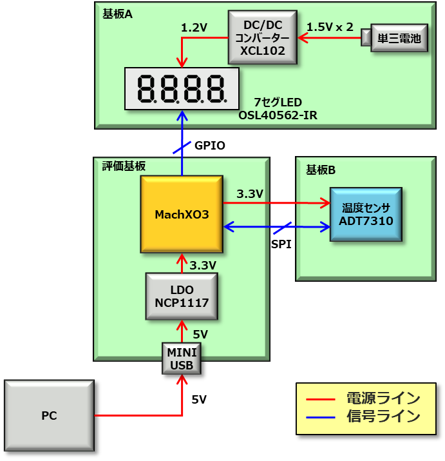
As a point, it will be 3.3V single drive, the 7 segment LED will be controlled by GPIO, and the temperature sensor will be controlled by SPI communication.
I plan to add a few more features when I have time to make this product. (For example, wireless communication, etc.)
This is the end of the first round.
Next time, I hope to actually use the FPGA design tool Lattice Diamond and check the operation of the evaluation board.
See you next time! Seeya!

About the Lattice FPGA Getting Started Blog
Throughout the article, we are making a module that converts the temperature (SPI communication) acquired by the temperature sensor inside the FPGA and displays it on the 7-segment LED display!
If you are interested in "What is this newcomer making?"
I would be happy if you could check the module production process and the whole picture from the page below!