- Semiconductor BusinessHOME
- Products and Services of Macnica,Inc.
-
technical information

-
Events and Seminars
- Handling Manufacturer
- Support
- Inquiry
- Click here to purchase products
- Semiconductor business e-mail magazine registration
![]()
![]() Narrow down by specifying conditions
Narrow down by specifying conditions
現在2189件がヒットしています。check

hello! I'm Ryosu, a new engineer on the Lattice team.
This time, I would like to check the operation of the XO3LF Starter Kit evaluation board using the Lattice design tool "Diamond".
Last time, we decided on the concept/function/usage and thought about the power line and signal line (block diagram).
Now that the concept has been solidified, let's actually touch the evaluation board!
To check the operation of the evaluation board, I would like to write a design to the FPGA that lights up the LED on the evaluation board.
Next, I would like to make a 7-segment LED board and check the operation to see if it lights up.
For those of you who are visiting this blog for the first time, let me give you a brief overview of this blog.
In this blog, I will introduce the process of making a temperature sensor that controls 7 segments with FPGA.
(If you're interested, I'll attach links to other episodes below, so please take a look!)
How to get a license and install tools
License acquisition method
First, we will acquire a license and install a design tool.
The license and tools can be installed free of charge from the official website of Lattice. (after account creation)
After logging into the account you just created, click Products>>Lattice Diamond.

From Licensing>>Diamond Software Free License in the middle of the page
Click Node-locked License.

Fill in the necessary information such as the MAC address and issue the license.

When the license was issued, the license was sent to the email address you entered in the form of "license_xxxx.dat"!
We will use it later, so just confirm that you received the email.
How to install Diamond Tools
Next is the design tool installation method.
Click Products>>Lattice Diamond.
Select the package according to the OS, check the Box and download.

After extracting the downloaded Zip file, install it.
The installation will proceed with the recommended settings.
Previously, I couldn't use Dimaond well because I messed around here...

Store the license file obtained earlier in a folder directly under C (eg C:\lscc\diamond\3.12\license).
Change the name of the license file to license_xxxx.dat → license.dat and store it.
The storage location of the license file is specified by the Windows environment variable, so if necessary, set the value of Windows "Edit system environment variables" >> environment variable LM_LICENSE_FILE.
In my case, the license storage location was already set in the environment variable, so it was okay, but if it was not set, it seems that I need to create a new one.

This completes license issuance and tool installation.
operation check
Checking the operation of the evaluation board
I would like to check the operation of the evaluation board from now on.
First, write the sample design on the evaluation board and check the operation.
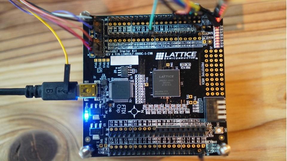
XO3LF is an easy-to-use FPGA that can operate at 3.3V and has a built-in configuration flash.
The evaluation board can write and power from USB Mini-B, supports 8 LEDs, DIP Switch, and about 80 I/O pins, so even beginners of FPGA can easily start evaluation. will be

The sample design uses an existing design that is used at the Diamond Tool Seminar that is held regularly.
The content of the design is a design that generates a ROM to control the lighting of the LEDs on the evaluation board and to observe the internal signals.

I made it possible to download the design file that I actually used, so if you are interested, please download it and write it on the evaluation board.
If you want to play around with Diamond tools but don't have a simple design, please download it!
Let's actually open the sample design!
Open the ".lpf" file in the file with Diamond.
Connect the PC and the evaluation board with a USB cable, and double-click the writing file JEDEC File from Diamond>>Process>>Export Files to generate the writing file.
After that, start Diamond >> Programmer, make various settings and write to the device.

Check that the LED on the top right of the evaluation board is lit after programming is complete.
These LEDs light up so that they pile up from the bottom to the top.
Since the LED lights up normally, I was able to confirm the operation safely.
With Diamond tools, various functions such as internal node observation tools, power consumption estimation tools, and RTL simulation tools can be used free of charge.
If you are curious about how to use the detailed Diamond tools! If there are many requests, I would like to post an article on how to use the Diamond tool separately.
So far, I tried moving the XO3LF evaluation board.
As an impression,
Many explanations in English! (smile)
I'm not good at English, so it takes time to check each one.
From now on, I have a feeling that this poor English will become an unexpectedly big problem when designing.
Next time, I would like to talk about checking the operation of the 7-segment LED board.
See you next time! See ya!

Inquiry
Please feel free to contact us if you have any questions about the evaluation board or sample design, or if there is anything you would like us to cover in this blog!
About rookie blog
This article focuses on LED control. But not just LED control
Throughout the article, we are making a module that converts the temperature acquired by the temperature sensor inside the FPGA and displays it on the 7-segment LED display!
If you are interested in "What is this newcomer making?"
I would be happy if you could check the module production process and the whole picture from the page below!
About Diamond Archive Seminar
Lattice design tool Diamond will be an archive seminar where you can learn for free.
In this archive seminar, we will introduce the basic usage of Lattice Diamond.
Since it is divided into the following items, it is possible to watch only the part that interests you.
-------------------------------------------
[Diamond Archive Seminar]
1.First of all
2. Create a project
3. RTL and IP generation
4. Logical simulation
5. Place and Route and Timing Constraint/Analysis
6. Programming
7. Internal Node Observation
-------------------------------------------
We would appreciate it if you could check it out from the page below!
Related information