- Semiconductor BusinessHOME
- Products and Services of Macnica,Inc.
-
technical information

-
Events and Seminars
- Handling Manufacturer
- Support
- Inquiry
- Click here to purchase products
- Semiconductor business e-mail magazine registration
![]()
![]() Narrow down by specifying conditions
Narrow down by specifying conditions
現在2168件がヒットしています。check

This time, in the 8th issue, we will introduce ``malfunction cases and solutions'' based on five representative cases. When designing the power supply part of an FPGA, various problems can occur. This is due to layout, peripheral components, sequence, pattern, etc.
We hope that you will find the examples of malfunctions introduced below and their solutions useful in your future FPGA power supply designs.
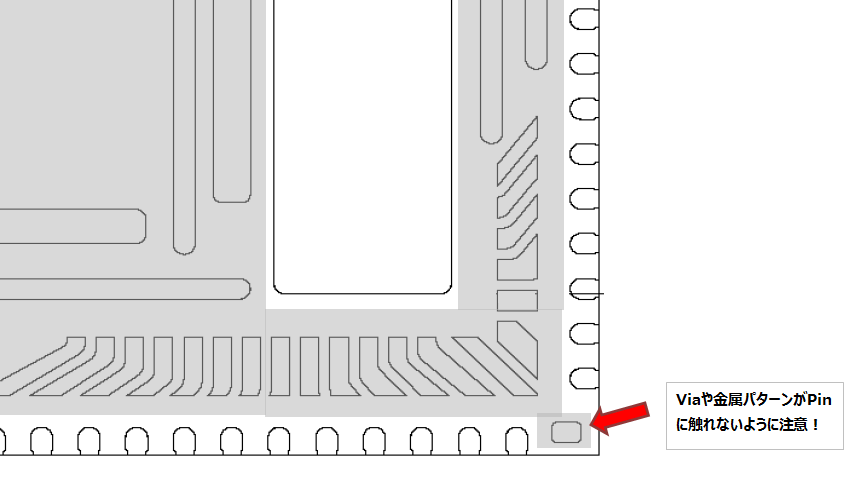
Case 1: Output failure due to layout
- Symptom: The output voltage waveform goes back and forth between specific voltages like a triangular wave.
- Cause: VIA was touching the pad in the area where pattern placement is prohibited on the back side.
- Countermeasure: Move the VIA and avoid drawing patterns in prohibited areas to achieve stable output.
- Note: Check the package section of the datasheet and avoid placing patterns or VIA in prohibited areas.
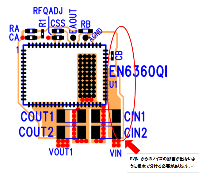
Case 2: Malfunction due to layout
- Symptoms: Movement but severe fever
- Cause: The AVIN extraction pattern that branches from VIN is close to the PVIN current loop and noise was riding on it.
- Countermeasure: By drawing a pattern from the root of VIN (Kelvin connection), noise contamination was alleviated and heat generation subsided.
- Note: Refer to pattern examples and design guides to create a pattern that minimizes noise ingress into the power supply and feedback.
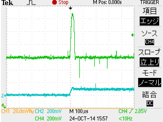
Case 3: Effects of peripheral parts
- Symptom: No output when power is turned on
- Cause: Overcurrent detection due to excessive output capacitance
- Countermeasure: Start normally by setting the output capacity appropriately
- Note: There is a maximum output capacitance value / Check the maximum capacitance value in each device data sheet
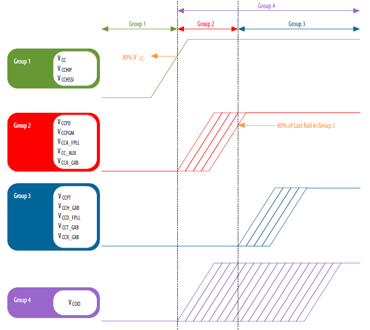
Case 4: Defect related to sequence
- Symptom: The output voltage starts to rise but drops halfway, and the power supply does not start up.
- Cause: Overcurrent was detected because the startup sequence was not followed and a current exceeding the limit was flowing during startup.
- Countermeasure: By following the startup sequence, unnecessary current was removed and the product started successfully.
- Note: Some of the Cyclone, Arria, and Stratix IV and V and later series have a startup sequence. / Refer to the Power-Up Sequence section in Power Management in the device handbook to properly startup each power supply line.
As described above, we hope that you will refer to the examples of problems and their solutions, and that they will be useful in your future FPGA power supply design.
If you would like to know more about malfunctions, please see the power supply column (summary of malfunctions and precautions).
In the next column, I will introduce using the PDN tool provided by Intel.