- Semiconductor BusinessHOME
- Products and Services of Macnica,Inc.
-
technical information

-
Events and Seminars
- Handling Manufacturer
- Support
- Inquiry
- Click here to purchase products
- Semiconductor business e-mail magazine registration
![]()
![]() Narrow down by specifying conditions
Narrow down by specifying conditions
現在2191件がヒットしています。check

In Part 7, we will explain what to keep in mind when selecting an FPGA power supply from the perspective of power supply specifications.
This time, we will once again introduce power supply selection for Cyclone® V (5CSXFC5D) as an example.
Check whether the selected power supply device is compatible with the following four items.
1. Output voltage accuracy
It is necessary to select a power supply device that meets the voltage accuracy introduced in the previous column.
For Cyclone🄬 V SX, the required voltage at VCC is 1.1V and a range of ±30mV is required.
- VCC voltage range is 1.07V-1.13V, ±2.72% variation range centered at 1.1V
- The voltage range of VCCA_FPLL is 2.375V-2.625V, ±5% fluctuation range when centering on 2.5V.
- IO voltage range is 1.71V-1.89V, ±5% fluctuation range when centered at 1.8V
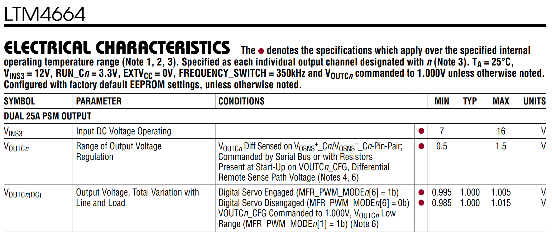
Intel Agilex 🄬 of the seriesSmart VIDcorresponds to The output voltage accuracy of the LTM4664 product with PMBus Interface is shown in Figure 1, an excerpt from the data sheet. It has a servo mode that makes the output voltage more accurate than a regular DC/DC converter. Under the condition of 1.0V output, the accuracy is within ±1.5% when servo mode is off, and within ±0.5% when servo mode is on.
Therefore, the Cyclone🄬 V SX's VCC voltage of 1.1V±30mV is a power supply device that can be used without any problems.
2. Output voltage ripple
It is necessary to select a power supply product that satisfies the Allowable Ripple of FPGA specifications.
As mentioned in the previous column, Allowable Ripple for each device on the Introduction sheet of the PDN tool (5% in this case)
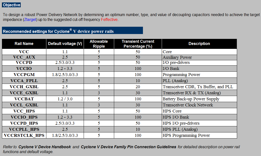
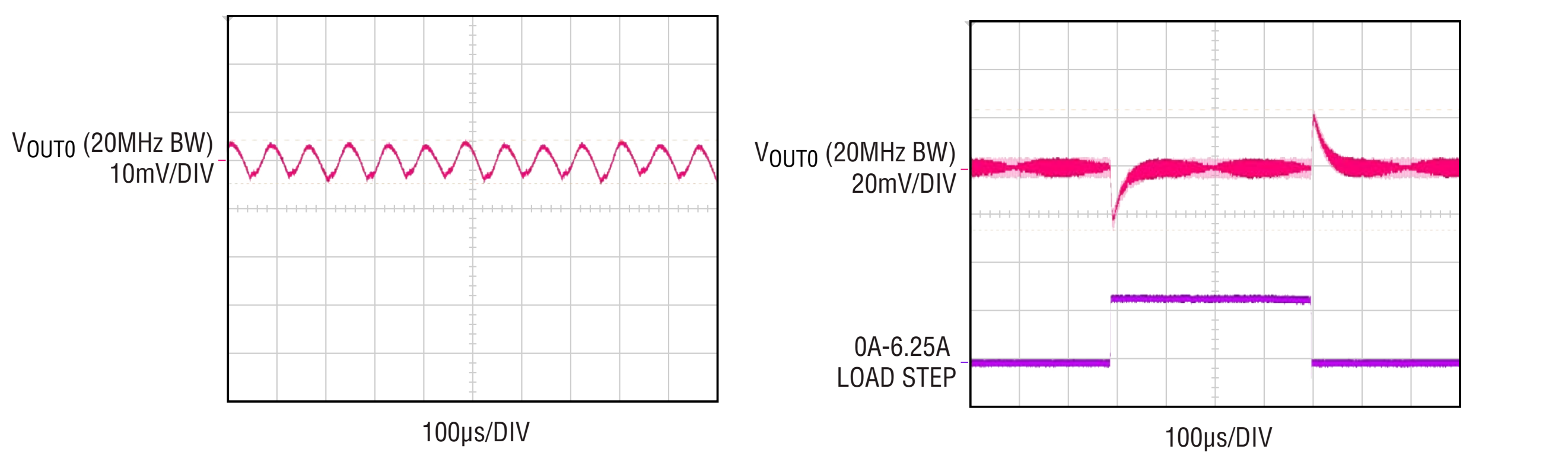
The FPGA's required voltage accuracy is set at Allowable Ripple5%, so it is necessary to check whether the ripple voltage and load response characteristics of the DC/DC converter are satisfied. The waveforms in Figure 3 are the ripple voltage and load response characteristics when outputting 1V. Both are within 5%, so there is no problem.
3. Checking the FPGA startup sequence
Configure the power supply so that VCC and VCCA_PLL start up in order (refer to the device handbook in the previous column).
For a typical DC/DC converter, select a power supply IC or module with PowerGood and Enable functions, or use an external sequencer to design a power supply that satisfies the sequence conditions required by the FPGA.
For the LTM4683, sequence times can be set using registers inside the module. Also, it has PowerGood and Enable (RUN Pin), so it satisfies the requirements.
4. Presence or absence of soft start
FPGA startup regulations include tRamp regulations (regulations for startup time), and it is necessary to select a power supply with specifications that fall within that range.
Some products have a fixed startup time on the device side, while others can be adjusted using an external capacitor (CSS), so we recommend choosing a DC/DC converter that allows you to adjust the startup time using an external capacitor. Masu.
For the LTM4683, the rise time can be set using registers inside the module.
In the above, we introduced the selection of power supply products that meet the power requirements of FPGAs.
By confirming this together with the previous column, it will be possible to develop more appropriate power supply products for FPGAs.