- Semiconductor BusinessHOME
- Products and Services of Macnica,Inc.
-
technical information

-
Events and Seminars
- Handling Manufacturer
- Support
- Inquiry
- Click here to purchase products
- Semiconductor business e-mail magazine registration
![]()
![]() Narrow down by specifying conditions
Narrow down by specifying conditions
現在2189件がヒットしています。check


hello.
My name is Intel F. Hanako and I provide technical support for Intel® FPGA products at Macnica.

Have you ever wondered this when compiling in Quartus® Prime?
"I want each entity to be arranged like fitting pieces of a puzzle."
"I want to fence only certain entities so that the layout is not cluttered."
In such cases, use a technique called Logic Lock.
Logic Lock allows the user to specify the layout of the entities themselves, so the work efficiency of the Quartus Prime Compiler can be improved, and compile time optimization can be expected. It can also be used in conjunction with incremental compilation techniques for even greater productivity gains.
Here are the basic steps for Logic Lock.
Logic Lock supported environments
Below are the environments where Logic Lock can be used.
| handle Quartus Prime |
Quartus Prime Pro Edition / Quartus Prime Standard Edition *Lite Edition is not supported |
| handle device family |
Device Families Supported by Quartus Prime Pro and Standard Edition |
Table 1. Logic Lock supported environments
Application examples where Logic Lock is effective
Logic Lock can be applied at various points in the design flow to help improve design productivity. for example,
- I want to arrange the cells of a certain subordinate entity to some extent rather than interspersing them.
- You want to decide the placement area for each entity you are in charge of, and reduce the placement conflicts when the entity is finally integrated.
At times like this, you get great benefits.
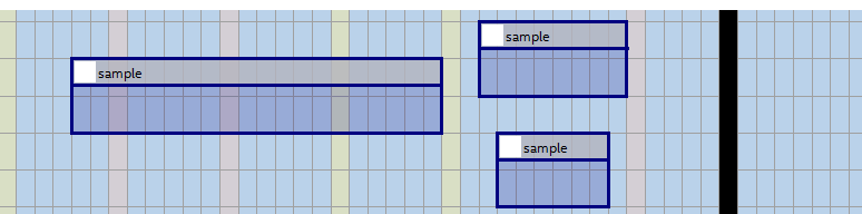
What is a Logic Lock region?
Create Logic Lock regions for the entities whose placement you want to control to control the layout of your design.
Due to the physical framework, even if there is a design or layout change in the surrounding entities, the placement of the entities specified in the Logic Lock region will not go out of the framework = will not be affected.
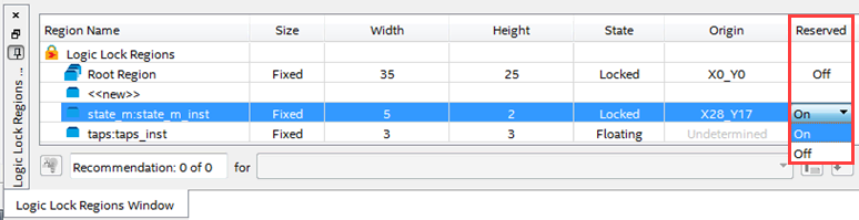
Reserved Logic Lock Region
Only entities and nodes assigned to the specified Logic Lock region can be placed, preventing resources from other entities from being placed together.
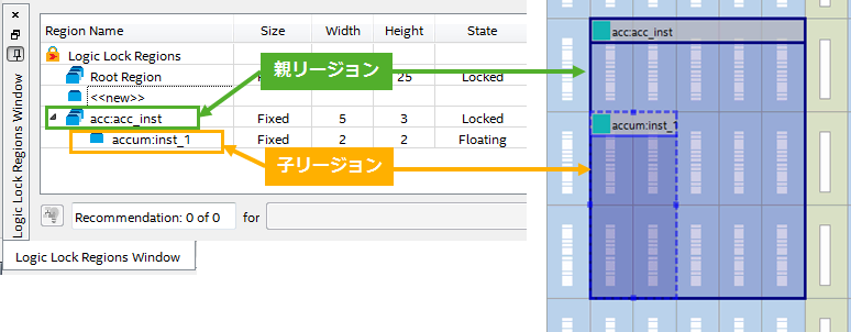
Parent Region/Child Region (Standard Edition only)
Logic Lock regions can have parent-child relationships (so-called “nesting”). Moving a parent region automatically moves the associated child regions. Child regions can be defined as floating or fixed within the parent region.
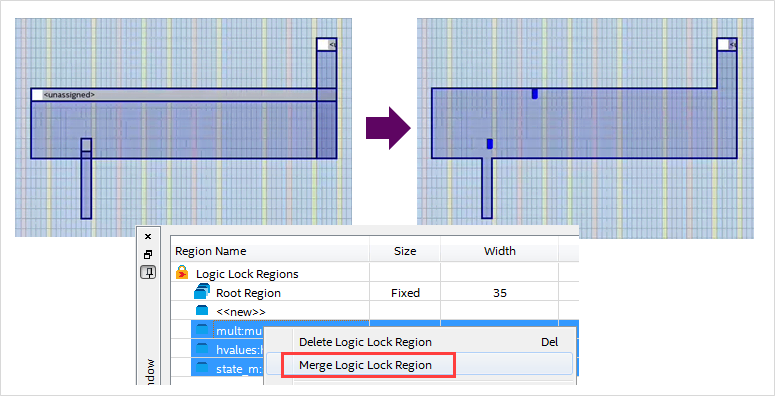
Merging Regions
You can merge multiple regions to specify a rectangular area.
Customizing Region Shapes
Areas can be added or deleted from the created region shape, and the original rectangular area can be specified. (Pro Edition only)
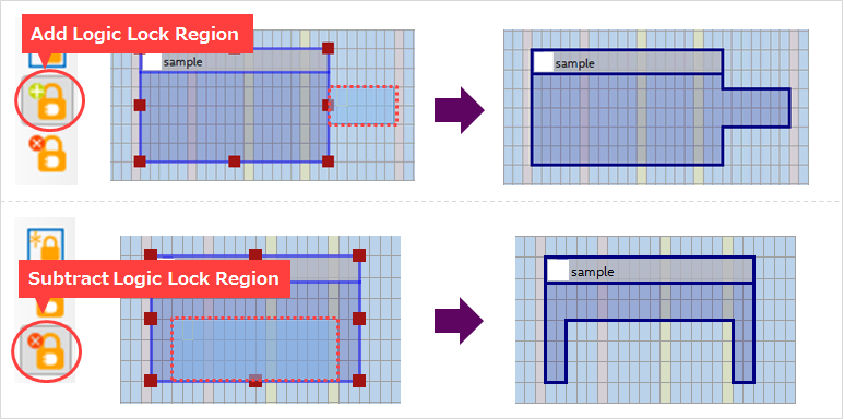
Using this function, it is possible to specify a non-contiguous area as a region.
In the Standard Edition, the Add/Subtract Logic Lock Region function cannot be used, but by setting multiple non-adjacent non-contiguous regions into one region using the Merge Logic Lock Region function, the non-contiguous regions can be defined.
Create a Logic Lock region
Create a Logic Lock region to set Logic Lock for subordinate entities in the Quartus Prime project. Since you are framing and arranging regions for the sub-entities of your design, you must know how many logic resources your entities require. Therefore, let's execute and complete the process above Analysis & Synthesis in advance.
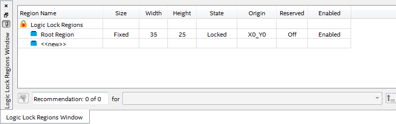
1. Bring up the Logic Lock Regions Window (Assignments menu) for creating regions.
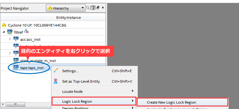
2. Right-click the entity you want to specify Logic Lock from the Project Navigator window > Logic Lock Region > Create New Logic Lock Region
Choose.
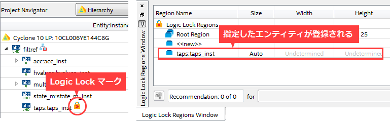
Make sure the specified entity is registered in the LogicLock Regions Window and marked in the Project Navigator window.
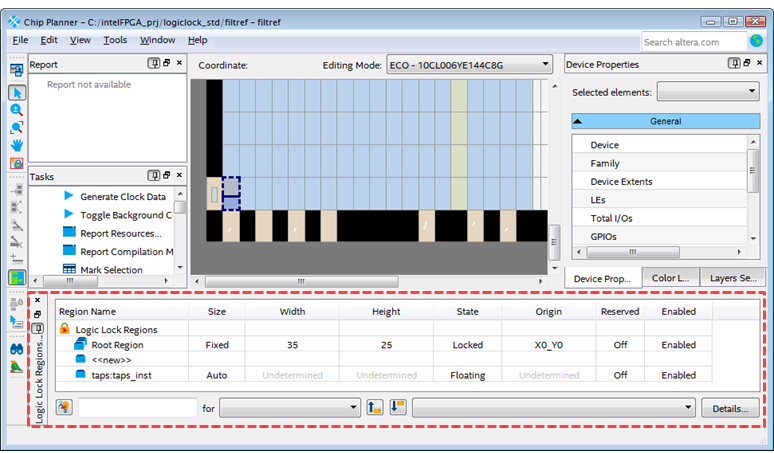
3. Launch Tools menu > Chip Planner.
From here on, use the Logic Lock Regions Window on the Chip Planner to make placement-aware settings.
If the Chip Planner does not show the Logic Lock Regions Window,
Select View menu > Logic Lock Regions Window on the Chip Planner.
4. Make various settings for the region.
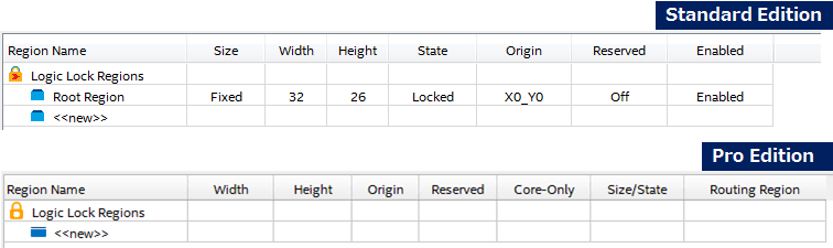
| column name | set value | overview |
| Size (Standard only) |
Auto | Quartus Prime determines the size based on the entity compilation results. |
| Fixed | Allows the user to specify the size of the region. | |
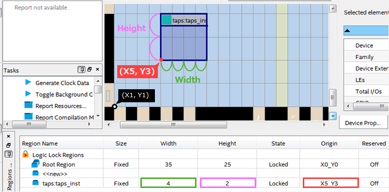
| Width | number of columns | Set the width of the area. |
| Height | number of rows | Sets the height of the region. |
| State (Standard only) |
Floating | Quartus Prime determines the location of regions on the device. Region borders are shown as dashed lines in the Chip Planner. |
| Locked | Fixed at a user-specified position. A locked region's Size must be Fixed. Region boundaries are displayed in practice on the Chip Planner. | |
| Origin | position/ Undetermined |
Sets the position of the Logic Lock region within the Chip Planner. Displays Undetermined when the State column is Floating. |
| Reserved | Off/On | Excludes placement of other entity's resources from the region. Not applicable to Routing Regions in Pro. |
| Enabled (Standard only) |
Enabled/Disabled | Specifies to enable/disable the region setting. |
| Core-Only (Pro only) |
Off/On | Exclude peripheral resources (I/O, HSSIO, PCIe, PLL, etc.) from the region. |
| Size/State (Pro only) |
Fixed/Locked | The user specifies the size and placement of the regions. |
| Auto/Floating | Quartus Prime determines the size and placement of regions. | |
| Routing Region (Pro only) |
Unconstrained (default) | Allows the fitter to use routes available on the device. |
| Whole Chip | Same as Unconstrained, but writes the constraints to the project settings file (.qsf). | |
| Fixed with Expansion | Follow the outline of the placement area. The routing area is scaled by a larger number of rows/columns than the placement area. | |
| Custom | You can create custom routing areas around regions. Routing regions can be moved independently on the Chip Planner, and it is also possible to select and move both placement and routing regions using the Shift key. |
Table 2. Logic Lock Region Attributes
run the compile
After setting the region, run compilation. (Apply incremental compilation if necessary.)
Processing menu > Start Compilation
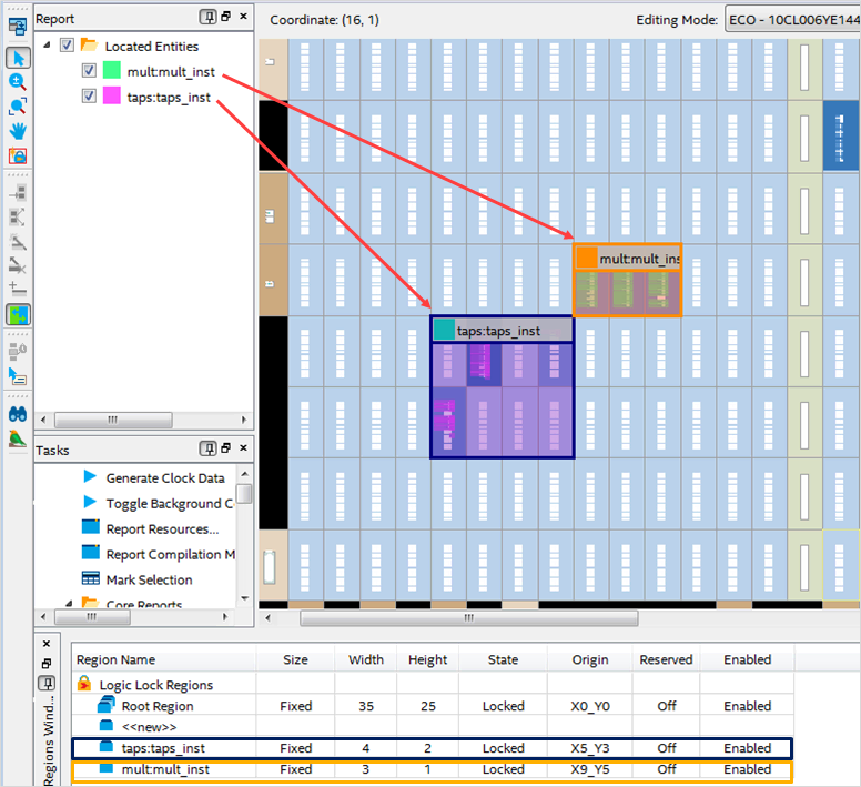
Check the compilation result
After compilation is complete, check the compilation report and Timing Analyzer to confirm that the timing requirements have been met, and the ChipPlanner to check the placement status.
At the end
How was it?
If you want to constrain resource placement on an entity-by-entity basis, make good use of Logic Lock.
Click here for recommended articles/materials
How to Apply Placement Constrained Subordinate Entities to Another Project (Overview)
How to recompile only part of the FPGA design
Try to use incremental compilation
Intel® FPGA Development Flow/FPGA Top Page