- 半導体事業HOME
- マクニカの製品・サービス
-
技術情報

-
イベント・セミナー
- 取扱メーカー
- サポート
- お問い合わせ
- 製品購入はこちら
- 半導体事業のメルマガ登録
![]()
![]() 条件を指定して絞り込む
条件を指定して絞り込む
現在2189件がヒットしています。check
在宅ワークの定着、クラウドへの接続、生成AIの普及、動画配信サービスなどの新しいエンターテイメントの普及により、インターネットトラフィックの劇的な増加が起こっています。高速、広帯域、大容量のネットワーク需要に対応するため伝送速度のアップグレードも進み、データセンターやインターネット接続事業者などのバックボーンネットワークにおいて400Gの採用・検討が進んでいます。
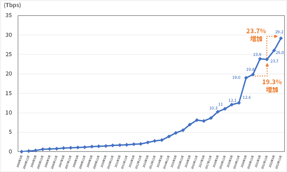
固定系ブロードバンド契約者の総ダウンロードトラヒック(推定値)(我が国のインターネットにおけるトラヒックの集計結果より引用)
そこで今回は400G対応の光トランシーバーモジュールの規格(フォームファクター)と光伝送規格について深堀してみます。シリーズ第1弾、100G編は次のリンクよりご覧ください。
高速化・小型化する光トランシーバーモジュール
前回の100G編の記事で紹介した通り、光トランシーバーモジュールは時代と共に伝送速度の高速化や小型化の要望に対応してきたため、さまざまなタイプがあります。以下の表1をご覧ください。
表1.伝送速度と光トランシーバーのフォームファクター
|
伝送速度(Gbps) |
フォームファクター |
|
1 |
SFP |
|
10 |
SFP+ |
|
25 |
SFP28 |
|
40 |
QSFP+ |
|
100 |
QSFP28 |
|
200 |
QSFP56 |
400G光トランシーバーモジュールのフォームファクター
400Gの光トランシーバーモジュールとして、50Gを8レーン束ねて400GとするQSFP-DDが規格化されました。DDとは、倍密度を意味するDouble Densityであり、50Gを4レーンで構成し200GとするQSFP56の倍ということです。なお、QSFP-DDはQSFP28と下位互換があるため、QSFP-DDのケージにQSFP28を接続できます。
その後、OSFPが規格化されました。OSFPはQSFP-DDよりもサイズが大きくなっており、放熱や内部回路の実装において、優位性があります。続いて、電気側の25G信号を16レーン束ねて400GとするCFP8が規格化されました。また近年では100G信号を4レーン束ねて400GとするQSFP112も規格化されました。
表2. 400Gに対応したフォームファクター
|
フォームファクター |
1レーン当たりの速度とレーン数(電気側) |
|
QSFP-DD |
50G×8レーン |
|
OSFP |
|
|
CFP8 |
50G×16レーン |
|
QSFP112 |
100G×4レーン |
現在、400Gのトランシーバーモジュールにおいては、QSFP-DDとOSFPが主流となっています。
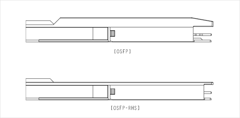
OSFPにはOSFPとOSFP-RHS(Riding Heat Sink)の2種類あります。これらの違いは光トランシーバーモジュールがヒートシンクを搭載するか、搭載しないか、です。OSFPはヒートシンクを搭載するため、ヒートシンクを搭載しないケージに接続可能です。一方、OSFP-RHSはヒートシンクを搭載しないため、ヒートシンクを搭載するケージに接続可能です。
表3.OSFP/OSFP-RHSと接続可能なケージ
|
フォームファクター |
ヒートシンクを搭載しないケージ |
ヒートシンクを搭載するケージ |
|
OSFP |
〇 |
× |
|
OSFP-RHS |
× |
〇 |
以下の図1がOSFPのMSAから参照したOSFPとOSFP-RHSの外形図です。ヒートシンクを搭載しないOSFP-RHSの高さが低いことがイメージいただけると思います。
図1.OSFP/OSFP-RHSの形状(OSFP MSA Rev5.0より引用)
400Gの光伝送規格
次に、光側の伝送規格を見ていきましょう。以下の表4は、400Gの光伝送規格をまとめたものです。
表4. 400G光伝送規格
|
通信距離 |
(C)多芯光ファイバー (MPOコネクター) |
(D)2芯光ファイバー (LCコネクター) |
|
|
(A)Multi-mode Fiber |
100m |
400GBASE-SR8 (IEEE P802.3cm) |
400GBASE-SR4.2 (IEEE P802.3cm) |
|
(B)Single-mode Fiber |
500m |
400GBASE-DR4 (IEEE P802.3bs) |
- |
|
2km |
400G DR4+ (100G Lambda MSA) |
400GBASE-FR4 (IEEE P802.3cu) |
|
|
10km |
4×100G LR4 (100G Lambda MSA) |
400G LR4-10 (100G Lambda MSA) |
|
|
120km |
- |
400G ZR (OIF 400ZR, amplified) |
|
|
1,000km |
- |
400G ZR+ (Open ZR+, amplified) |
表4の分類について説明します。まず上から2行目(A)はMulti-mode Fiberを使用する規格です。3-7行目(B)はSingle-mode Fiberを使用する規格で、最大通信距離によって分類しています。また表4の左から3列目(C)は多芯光ファイバーを使用する規格です。4列目(D)は2芯光ファイバーを使用する規格です。
上記の規格は、以下のような団体によって標準化されています。
・米国電気電子学会のIEEE802.3 Ethernet Working Group
・いくつかの光トランシーバーモジュールメーカーによるMulti Source Agreement(MSA)やその他のアライアンス
・光ネットワーク機器や関連するコンポーネントベンダーなどが参加している光ネットワーク技術を推進する団体(OIF)
伝送距離でみる4つの代表規格
400G光トランシーバーモジュールの代表的な光の伝送規格として、(1)短距離用のSR8、(2)(3)中距離用のDR4/FR4、(4)長距離用のLR4-10があります。
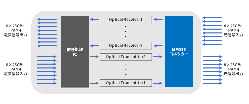
(1)短距離用の400GBASE-SR8
SR8の8は、光信号が8レーンであることを示します。つまり、光信号は50G×8レーンの構成です。現在、伝送距離が100m以内の短距離接続にはこの400GBASE SR8(図2)が多く使用されています。
なお信号の変調方式はPAM4(Pulse Amplitude Modulation)を用います。NRZは1つのシンボルで1ビットを伝送するため、2値信号の伝送となります。一方、PAM4は1つのシンボルで2ビットを伝送するため、4値信号の伝送となります。実際にそれぞれの波形が下記の図3となります。
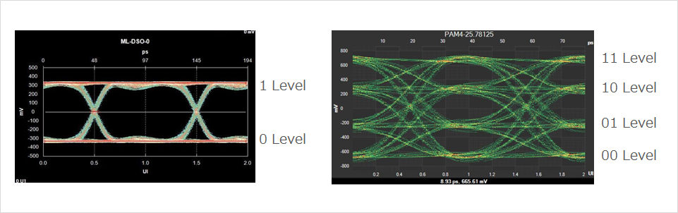
NRZは2つの電圧レベル(2値信号)となり、PAM4は4つの電圧レベル(4値信号)であることが分かると思います。400G通信では、変調方式にPAM4を用いることで伝送速度を向上しています。
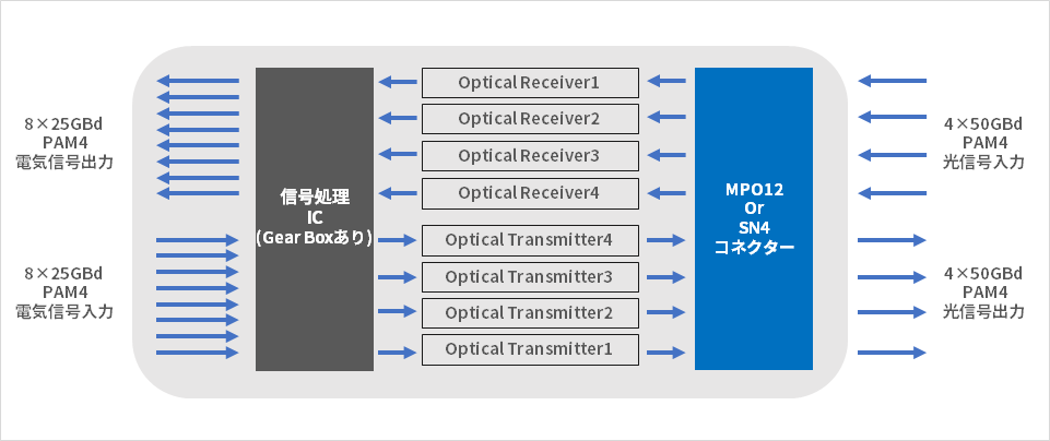
(2)(3)中距離用の400GBASE-DR4と400GBASE-FR4
つづいて、光信号が4レーンで伝送距離が500m以内の「400GBASE-DR4」、2km以内の「400GBASE-FR4」という光伝送規格を紹介します。
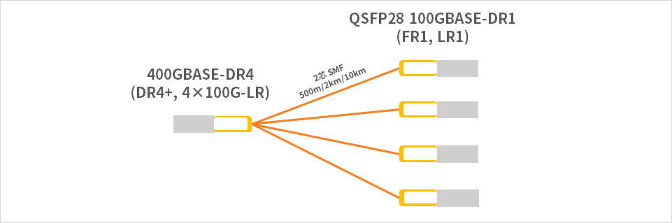
DR4の4は、光信号が4レーンであることを示し、100G×4レーンの構成になります。しかし、フォームファクターがQSFP-DDやOSFPの場合、電気信号は50G×8レーンの構成となっております。そのため1レーンあたりの伝送速度の変換が必要となり、変換を行う部品としてGear Box(ギアボックス)と呼ばれる部品が搭載されます。
以下の図5のように光伝送規格が100GBASE-DR1の光トランシーバーを4つ用いることで、ブレイクアウトすることも可能です。
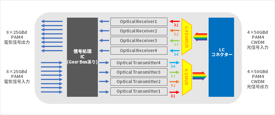
FR4はDR4と同様に光信号が4レーンあり、100G×4レーンの構成になります。しかし、DR4と異なり、2芯の光ファイバーで伝送します。伝送距離が500m以内のDR4ではリボンファイバーを使いますが、伝送距離が2km以内のFR4では、WDM(Wavelength Division Multiplexing:波長分割多重)という技術を使って、4レーンの光信号を多重して1本の光ファイバーで送ります(図6)。
まず送信側では4レーンの光波長を少しずつずらし、光合波器(MUX)で4つの光信号を多重化させて、1本の光ファイバーで送信します。一方、受信側では分波器(DeMUX)により光波長を分離し、各レーンの信号で受信できるようになっています。
(4)長距離用の400G LR4(-10)
400G LR4は伝送距離が10km以内の光伝送規格です。このLR4はFR4同様に、100G×4レーンの構成かつWDM技術を用いています。
より長距離の400G ZR/ZR+
より伝送距離の長い伝送規格として、ZR/ZR+があります。ZR/ZR+では上述のPAM4と異なるDP-16QAMという変調方式を採用しています。この400G ZR/ZR+については、下記リンクの技術記事にて詳細をご確認ください。
おまけ
100Gから400Gに装置をアップグレードした際にすでに敷設している光ファイバー(コネクター)をリユースしたい場合、下記の通り、400Gから100Gに下位互換として相当する光の伝送規格の種類をまとめてみました。
表5. 下位互換として相当する100G光伝送規格と400G光伝送規格
|
通信距離 |
多芯光ファイバー (MPOコネクター) |
2芯光ファイバー (LCコネクター) |
|
|
Multi-mode Fiber |
100m |
400GBASE-SR8 (IEEE P802.3cm) |
400GBASE-SR4.2 (IEEE P802.3cm) |
|
Single-mode Fiber |
500m |
400GBASE-DR4 (IEEE P802.3bs) |
- |
|
2km |
400G DR4+ (100G Lambda MSA) |
400GBASE-FR4 (IEEE P802.3cu) |
|
|
10km |
4×100G LR (100G Lambda MSA) |
400G LR4-10 (100G Lambda MSA) |
|
|
120km |
- |
400G ZR (OIF 400ZR amplified) |
|
|
1,000km |
- |
400G ZR+ (Open ZR+ amplified) |
表5で緑色にハイライトしている光伝送規格は、100Gと400Gで最大伝送距離が同じでも、使用する光コネクター等が異なるため、相当する100Gの光伝送規格は現状ありません。
一方、赤色にハイライトしている光伝送規格の100G CWDM4であれば、400GBASE-FR4が相当します。また、100GBASE-LR4であれば400G LR4-10が相当します。そのため、現在100Gを採用しており、採用中の光ファイバーなどを活用して400Gにアップグレードすることを検討している場合、光トランシーバーモジュール等も確認いただく必要があります。
400G光トランシーバーモジュールの伝送規格について解説しました
この記事では、400G対応の光トランシーバーモジュールのフォームファクターと光伝送規格に焦点をあてて説明しました。100G編、800G編の記事もございますので、是非ご覧ください。
100G編:https://www.macnica.co.jp/business/semiconductor/articles/coherent/144352/
800G編:https://www.macnica.co.jp/business/semiconductor/articles/coherent/145049/
マクニカでは、光トランシーバーモジュールのリーディングカンパニーである Coherent社のFinisar Transceiverシリーズをご提案しております。経験豊富な営業と光トランシーバーモジュール製品専属の技術スタッフがお客様の検討から導入、運用までを一貫してサポートします。ご興味のあるお客様は、ぜひ以下のフォームよりお問い合わせください。


この記事もよく読まれています