- Semiconductor BusinessHOME
- Products and Services of Macnica,Inc.
-
technical information

-
Events and Seminars
- Handling Manufacturer
- Support
- Inquiry
- Click here to purchase products
- Semiconductor business e-mail magazine registration
![]()
![]() Narrow down by specifying conditions
Narrow down by specifying conditions
現在2175件がヒットしています。check

Optical transceiver modules are one of the important components that make up optical transmission networks. There are many different types because there have been many changes over the years in response to demands for higher speeds and smaller sizes.
In this article, we will focus on the 100GbE optical transceiver module, which is currently widely used in data centers and optical communications fields, and look back on its history while delving into the 100GbE standard.
Optical transceiver modules becoming faster and smaller
The first optical transceiver module compatible with 1GbE (1Gbps Ethernet), GBIC (Gigabit Interface Converter), was standardized in 1995. That was almost 30 years ago. Since then, optical transceiver modules have responded to demands for faster transmission speeds and smaller sizes.
Currently, the module standard (form factor) called SFP (Small Formfactor Pluggable) is the mainstream, and there are several types depending on the transmission speed.
|
Transmission speed (GbE) |
SFP form factor |
|
1 |
SFPs |
|
10 |
SFP+ |
|
25 |
SFP28 |
|
40 |
QSFP+ |
|
100 |
QSFP28 |
Table 1. Transmission speed and SFP form factor
The mainstream in 100G is QSFP28
Discussion on 100G started in 2006, but 100GbE was standardized along with 40GbE in 2010. Initially, 100GbE was standardized as "CFP" and "CFP2", which bundled 10 lanes of 10GbE signals on the electrical side to create 100GbE (10GbE x 10 lanes), and later bundled 4 lanes of 25GbE (25GbE x 4 lanes). "CFP4" and "QSFP28" have been standardized.
|
Speed and number of lanes per lane (electric side) |
form factor |
|
10GbE x 10 lanes |
CFP |
|
CFP2 |
|
|
25GbE x 4 lanes |
CFP4 |
|
QSFP28 |
Table 2. Supports 100G by bundling multiple lanes
For 100GbE, the market volume of QSFP28 is overwhelmingly large, so many users are switching to QSFP28 due to availability and cost considerations. As a result, QSFP28 has become the mainstream form factor for optical transceiver modules that support 100G.
Optical transmission standards for many 100G optical transceiver modules
After introducing the module standards, we will explain the optical transmission standards. Table 3 summarizes the optical transmission standards.
The table is divided into communication distance on the vertical axis, ``multi-core optical fiber,'' which uses multi-core optical fibers, and ``two-core optical fiber,'' which uses two optical fibers. The horizontal axis classifies those using multimode optical fiber and those using single mode optical fiber based on communication distance. As you can see in Table 3, there are many optical transmission standards.
|
Communication distance |
Multicore optical fiber (MPO connector) |
2-core optical fiber (LC connector) |
|
|
Multi-mode Fiber |
100m |
100GBASE-SR10 (IEEE802.3ba) – CFP/CFP2 100GBASE-SR4 (IEEE802.3bm) – CFP4/QSFP28 100GBASE-SR2 (IEEE802.3cd) - SFP-DD |
100G SWDM4 (SWDM Alliance) – QSFP28 100G SRBD (Cisco, ARISTA) – QSFP28 |
|
300m |
100G-eSR4 (proprietary to each company) – QSP28 |
||
|
Single-mode Fiber |
500m |
100G PSM4 (100G PSM4 MSA) QSFP28 |
100G CWDM4-OCP (Facebook) – QSFP28 100GBASE-DR (IEEE802.3cd) – SFP-DD |
|
2km |
- |
100G CWDM4 (CWDM4 MSA) – QSFP28 100G FR (100G Lambda MSA) - SFP-DD |
|
|
10km |
- |
100GBASE-LR4 (IEEE802.3bm) – CFP4/QSFP28 100G eCWDM4 / 4WDM-10 (4WDM MSA) – QSFP28 100G LR (100G Lambda MSA) – SFP-DD |
|
|
20km |
- |
100G eLR4 / 4WDM-20 (4WDM MSA) – QSFP28 |
|
|
40km |
- |
100GBASE-ER4 (IEEE802.3bm) – CFP2 100G ER4f / 4WDM-40 (4WDM MSA) – QSFP28 |
|
|
80km |
- |
100G ZR4 (proprietary to each company) – QSFP28 100G COLORZ (Inphi) – QSFP28 |
|
|
120km |
- |
100G DCO (proprietary to each company) – CFP2/QSFP28 |
Table 3. Summary of 100G optical transmission standards
These standards are standardized and developed by the following organizations:
・Standardized by the IEEE802.3 Ethernet Working Group of the Institute of Electrical and Electronics Engineers of America
・Developed through Multi Source Agreement (MSA) and other alliances between several optical transceiver module manufacturers
・Original standards of each manufacturer
Below is a brief introduction to the MSA standard.
Three representative players based on transmission distance...100GBASE SR4, LR4, ER4
Typical 100GbE optical transceiver modules include SR4 for short distances, LR4 for long distances, and ER4 for even longer distances.
Before starting with the short-range SR4, let's take a look at the first 100GbE optical transceiver module, the SR10.
First realized 100GBASE-SR10
"100GBASE-SR10" (*1) is a standard called "100GBASE-SR10" that transmits 100m using 24-core ribbon fiber, and the form factor is CFP or CFP2.
(* 1) The standard standardized by IEEE802.3 or the standard under discussion for standardization is called "100GBASE".
The S in SR10 means short range. The 10 in SR10 indicates that the optical signal has 10 lanes. In other words, the optical signal consists of 10 GbE x 10 lanes.
100GBASE-SR4 for short distances with 4 lanes
Technology has advanced since then, and "100GBASE-SR4", which consists of 25GbE x 4 lanes, has been standardized. The 4 in SR4 indicates that the optical signal has 4 lanes. In other words, the optical signal consists of 25GbE x 4 lanes.
The number of light-emitting laser elements and receivers has been reduced from 10 (SR10) to 4 (SR4), resulting in significant miniaturization. The form factor is CFP4 or QSFP28, and like the SR10, it transmits 100m. Currently, this QSFP28 100GBASE-SR4 (Figure 1) is often used for short-distance connections within 100m.
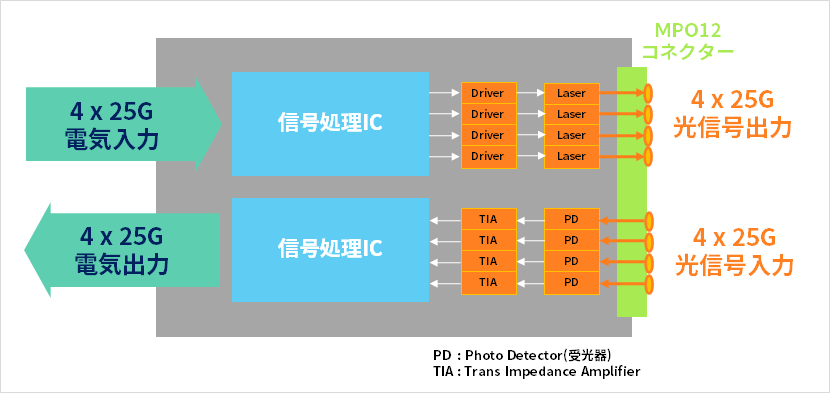
Figure 1. 100G SR4 block diagram
100G LR4 for long range and 100G ER4 for ultra long range
Subsequently, ``100GBASE-LR4'', which transmits 10km with four optical signal lanes, and ``100GBASE-ER4'', which transmits 40km, were standardized for long-distance connections. L in R4 stands for long distance (Long), E in E R4 stands for extended long distance (Extended), and transmission is performed using two-core optical fiber.
I mentioned that ribbon fiber is used for SR4, which transmits 100m, but for LR4 and ER4, which transmit long distances such as 10km or 40km, using ribbon fiber is not practical due to operational and cost considerations.
Therefore, we use a technology called WDM (Wavelength Division Multiplexing) to multiplex four lanes of optical signals and send them over a single optical fiber (Figure 2).
This technology uses an optical multiplexer (MUX) to multiplex four different signals onto a single optical fiber by slightly shifting the wavelengths of the four lanes of light. On the receiving side, on the other hand, an optical demultiplexer (DeMUX) is used to separate the signals into different wavelengths and separate them into signals for each lane. Click here to learn more about WDM.
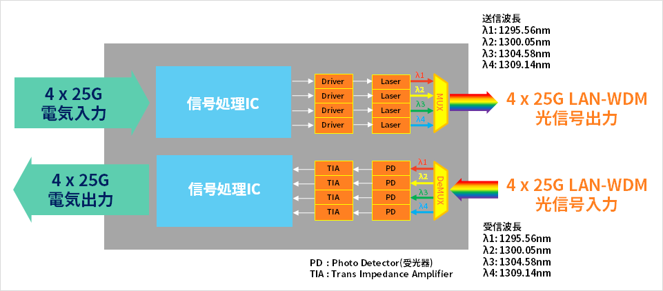
Figure 2. 100G LR4 / ER4 block diagram
To reduce the cost of optical transceiver modules, many optical transmission standards use FEC (Forward Error Correction) to perform error correction. With FEC, redundant bits are added on the transmitting side to detect and correct errors, and errors that occur during transmission are corrected on the receiving side. Using FEC has the advantage of reducing the cost of optical components.
However, LR4 does not specify the use of FEC. We use a high-performance laser and receiver to extend the transmission distance to 10km without using FEC.
MSA standards that meet various demands
The Multi Source Agreement (MSA) standard, which was briefly mentioned above, is a standard for optical transceiver module products agreed upon by multiple manufacturers. We will introduce three of these MSA standards.
1. 100G CWDM4
Many users, including Hyper Scale Data Center, have told us that SR4's 100m transmission distance is not enough, but LR4's 10km is not necessary. There was also a request that it would be nice if it was cheaper. CWDM4, which has a transmission distance of 2km, was proposed as a 100G optical transceiver module that satisfies these demands.
In LR4, the laser wavelength spacing was 800 GHz (approximately 4 nm), whereas in CWDM4, the wavelength spacing was widened to 20 nm, eliminating the need for a complex wavelength control mechanism. (Figure 3)
Additionally, by limiting the transmission distance from 10km to 2km, we are now able to use inexpensive lasers instead of expensive ones.

Figure 3. Wavelength arrangement of LR4 and CWDM4
2. 100G ER4f
In the explanation of 100GBASE-LR4, which is for long distance use, I mentioned that LR4 does not specify the use of FEC. The extended long range ER4 also does not specify the use of FEC. In order to extend the transmission distance to 40 km without using FEC, we use a more powerful laser and receiver.
However, the MSA standard called ER4f (or 4WDM-40) is an application of FEC to ER4 that has made it more compact and lower in cost. You may see optical transceiver modules sold as "QSFP28 100G ER4" on the web, but most of them cannot transmit 40km without FEC, and the limit is 25km to 30km. In other words, even though it is called ER4, it is actually "ER4f" so be careful.
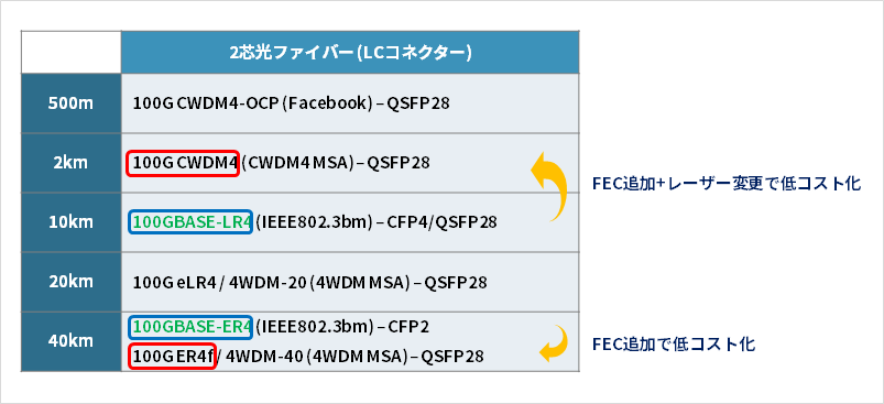
Figure 4. CWDM4 and ER4f, which are lower cost versions of LR4 and ER4.
3. 100G SWDM4
SR4 uses a 12-core ribbon fiber to transmit 100m. SWDM4 was proposed in response to the desire to transmit using 2-core multimode fiber instead of ribbon fiber.
100G SWDM4 is a technology that applies WDM, which was previously a technology for long wavelength bands, to short wavelength bands for transmission using two-core fibers.
The biggest advantage of 100G SWDM4 is that you can upgrade from 10G to 100G without changing the fiber from 10G SR, which uses 2-core multimode fiber.
Both transmission methods use 2-core multimode fiber, so the fiber can be used as is.
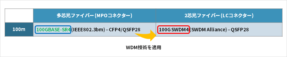
Figure 5. SWDM4 applying WDM technology to SR4
Also available for distances over 40km
100G ER4f transmits 40km, but ZR4 is a version that further increases the optical transmission power and improves reception sensitivity to achieve longer distances. Z R4's Z means that it has a longer range than Extended E, and 4 means that it is WDMing 4 lanes.
The 100G ZR has also been released, which offers even longer range than the ZR4. The Z in 100G ZR stands for ultra-long range, just like the ZR4, but there is no 4 behind it like in the ER4 and ZR4. This is because light is transmitted using a method different from wavelength multiplexing four wavelengths using WDM, such as ER4 and ZR4. Specifically, 100G ZR uses a modulation method called DP-QPSK to transmit light using only one wavelength. I would like to tell you more about 100G ZR in another article.
We explained the transmission standards for 100G optical transceiver modules.
This article focuses on the 100GbE optical transmission standard of optical transceiver modules. We also have articles on 400G and 800G, so please take a look.
400G Edition: https://www.macnica.co.jp/business/semiconductor/articles/coherent/144904/
800G edition: https://www.macnica.co.jp/business/semiconductor/articles/coherent/145049/
Macnica is proposing the Finisar Transceiver series from Coherent, a leading company in optical transceiver modules. Our experienced sales staff and technical staff dedicated to optical transceiver module products will support you from consideration to implementation and operation. If you are interested, please contact us using the form below.


This article is also often read