
![]()
![]() Narrow down by specifying conditions
Narrow down by specifying conditions
現在1887件がヒットしています。check

In recent years, WDM (Wavelength Division Multiplexing) technology has come to be used for optical communication as the amount of communication increases.
Among those who measure optical signals and those who use optical transceiver modules, I believe that there are those who have the following issues regarding WDM.
- Considering communication using WDM
- Communication failure of WDM transmission is occurring
Therefore, in this technical article, we will introduce what WDM is and the evaluation solution that can be recommended in the event of a transmission failure for beginners in optical communication.
What is WDM
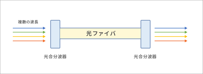
WDM (Wavelength Division Multiplexing) is a technology that uses multiple wavelengths to simultaneously transmit various information over a single optical fiber. Also known as wavelength division multiplexing. This technology can increase the transmission speed.
WDM transmission failure causes
If a communication failure occurs during transmission using WDM technology, the possible causes are as follows.
- Insufficient power per wavelength
- Interference between wavelengths
- Wavelength mismatch between transmitter and receiver
In order to analyze and prevent such causes, we recommend the following optical signal evaluation solution.
Optical signal evaluation solution that can also be used for communication using WDM
This solution uses products provided by II-VI (former Finisar) for evaluation.
Two features of the optical signal evaluation solution
- When a communication failure actually occurs, it is possible to analyze the cause from the approach of checking the state of the optical signal spectrum.
- You can estimate the loss of light not only after the problem has occurred, but also from the transmission distance and the number of connectors.
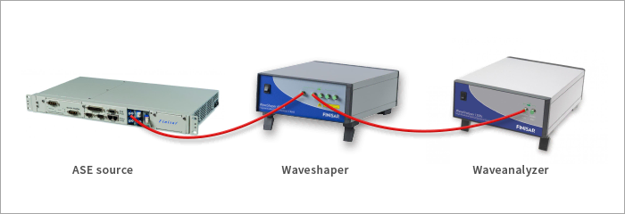
Product used (1): Waveshaper
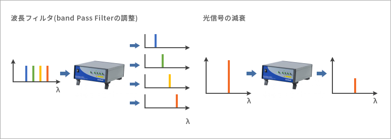
It can be widely used as a programmable optical filter and optical switch for R&D and manufacturing test applications of optical technology applied products. In addition, since the filter characteristics can be finely adjusted, it is possible to adjust the center wavelength, bandwidth, spectrum shape, and light attenuation rate.
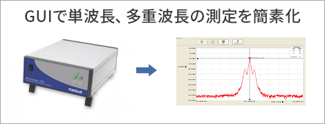
Product used (2): Waveanalyzer
This optical spectrum analyzer supports real-time measurement with extremely high resolution, and is best suited mainly for R&D of optical technology applied products and mass production testing at factories. Coherent detection technology using II-VI (formerly Finisar) in-house lasers, proven in optical transceivers, enables picometer resolution spectrum analysis and real-time measurements up to 10Hz.
*The measurable wavelength band is C-band.
Usage example: Verification without preparing several kilometers of optical fiber
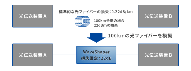
By using this solution, Waveshaper can be used to simulate the transmission line loss, making it possible to conduct preliminary verification without preparing several kilometers of optical fiber. It also helps prevent future problems.
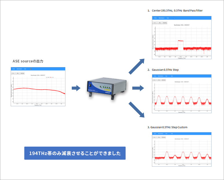
Actual use (1) Confirmation of ASP light source
The output of the ASE (Amplified Spontaneous Emission) light source was filtered with a Waveshaper, and the spectrum was confirmed with a Waveanalyzer. Spectrum created the following 3 patterns.
- Center 193.5THz, bandwidth 0.5THz
- Gaussian 0.5THz Step (7 pulse)
- Gaussian 0.5THz Step custom (7 pulse & 194THz band only attenuation)
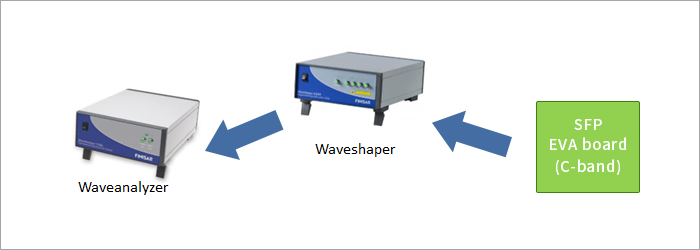
Device configuration
result
As you can see from the figure below, all three patterns were able to operate as they were set.
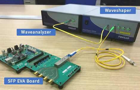
Actual use (2) Optical transceiver output measurement
Next, we measured the output power of the optical transceiver module.
Device configuration
It is a configuration that only changes the ASE source part of the test that was done earlier to the optical transceiver module.
result
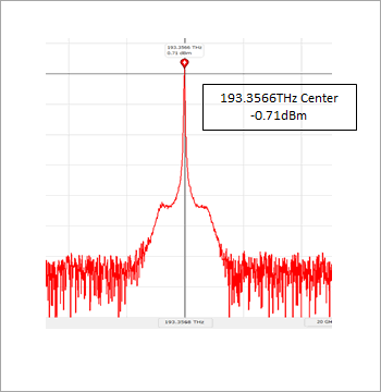
First, I measured the optical output of the optical transceiver module (SFP Module) with a Waveanalyzer.
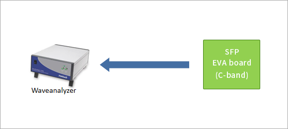
The characteristics of the light source of this SFP Module were Center 193.3566THz and the optical output was -0.71dBm.
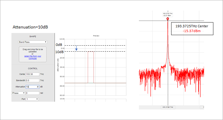
Furthermore, I applied 10dB attenuation to the optical output of the SFP Module. The optical output is -15.37dBm, and it can be seen that it is attenuated as set.
Now let's use Waveshaper to manipulate the optical spectrum.
The figure below is a spectrum waveform with a simple Waveshaper in between. The Band Pass Filter at this time is 0.5THz bandwidth with 193.38THz Center. At that time, the optical output was -5.24dBm at 193.3853THz center.
From this result, I was able to confirm that Waveshaper's Insertion Loss is 4.5db (typ) as specified. Waveshaper setting screen on the left, Waveanalyzer measurement screen on the right.
We are also renting out the solutions we introduced.
This time, we introduced an optical signal evaluation solution that can also be used for communication using WDM. In addition to the functions introduced in this article, it has many functions such as a function to reproduce the spectrum during modulation and a function to synthesize multiple wavelengths.
If you would like to check the detailed specifications, please click here.
Waveshaper
Waveanalyzer
Inquiry
In addition, for those who cannot decide to introduce the product based on the actual feeling of use, we also lend solutions. If you are interested, please contact us using the form below.
Click here for recommended articles/materials
What is an optical transceiver module?
Items required for testing optical transceivers