- Semiconductor BusinessHOME
- Products and Services of Macnica,Inc.
-
technical information

-
Events and Seminars
- Handling Manufacturer
- Support
- Inquiry
- Click here to purchase products
- Semiconductor business e-mail magazine registration
![]()
![]() Narrow down by specifying conditions
Narrow down by specifying conditions
現在2183件がヒットしています。check
Introduction
In order to realize advanced autonomous driving, the adoption of Ethernet for in-vehicle networks is increasing. However, there may be many people who have never been involved in development using Ethernet products.
In this article, we will introduce the basics of automotive Ethernet PHY/Switch in 3 episodes for those who do not know Ethernet.
What is Ethernet
Ethernet is a wired LAN communication standard used in homes and offices. Various communication standards are stipulated by an organization called IEEE, and the one standardized as IEEE802.3 is called Ethernet. IEEE802.3 defines Layer 2 (data link layer) and Layer 1 (physical layer) of the OSI reference model.
Trends in in-vehicle Ethernet
There is a keyword such as CASE as a future trend in the automobile industry. Connected, Autonomous, Share & Service, and Electric respectively. Among these, in-vehicle Ethernet is attracting increasing attention in relation to Connected and Autonomous. In the future, in order to realize more advanced autonomous driving, it is necessary to be able to handle more information, and it is necessary to be able to support a wider band than the current communication environment.
In that case, Ethernet may be suitable. The main reasons are as follows.
・Supports a wide range of communication bands
・Protocols can be unified
Automotive Ethernet standard
Four Ethernet standards are shown in the table. There are standards for consumer and automotive use, but the feature of the automotive use is that two-way communication is possible with a pair of twisted pair cables. This makes it possible to reduce the weight of the harness, which also has the advantage of reducing the weight of the vehicle. For automotive applications, the 100Mbps communication standard is IEEE 802.3bw, and the 1Gbps communication standard is IEEE 802.bp.
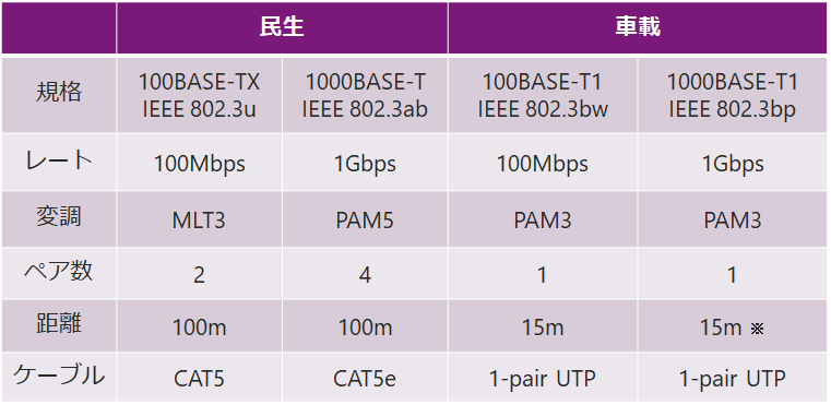
*Optional 40m support
In the second half of 2020, a Multi Gigabit Ethernet standard (IEEE 802.3ch) that supports bandwidths exceeding 1 Gbps will be established and is expected to become widespread in the future.
What is PHY
It stands for Physical Layer in the OSI reference model, and refers to the devices required to implement the functions of the physical layer. The role of PHY is to perform signal conversion so that the signal can be sent to the opposite device correctly. Therefore, it is necessary to use a PHY that complies with each standard.
About 100BASE-T1 PHY
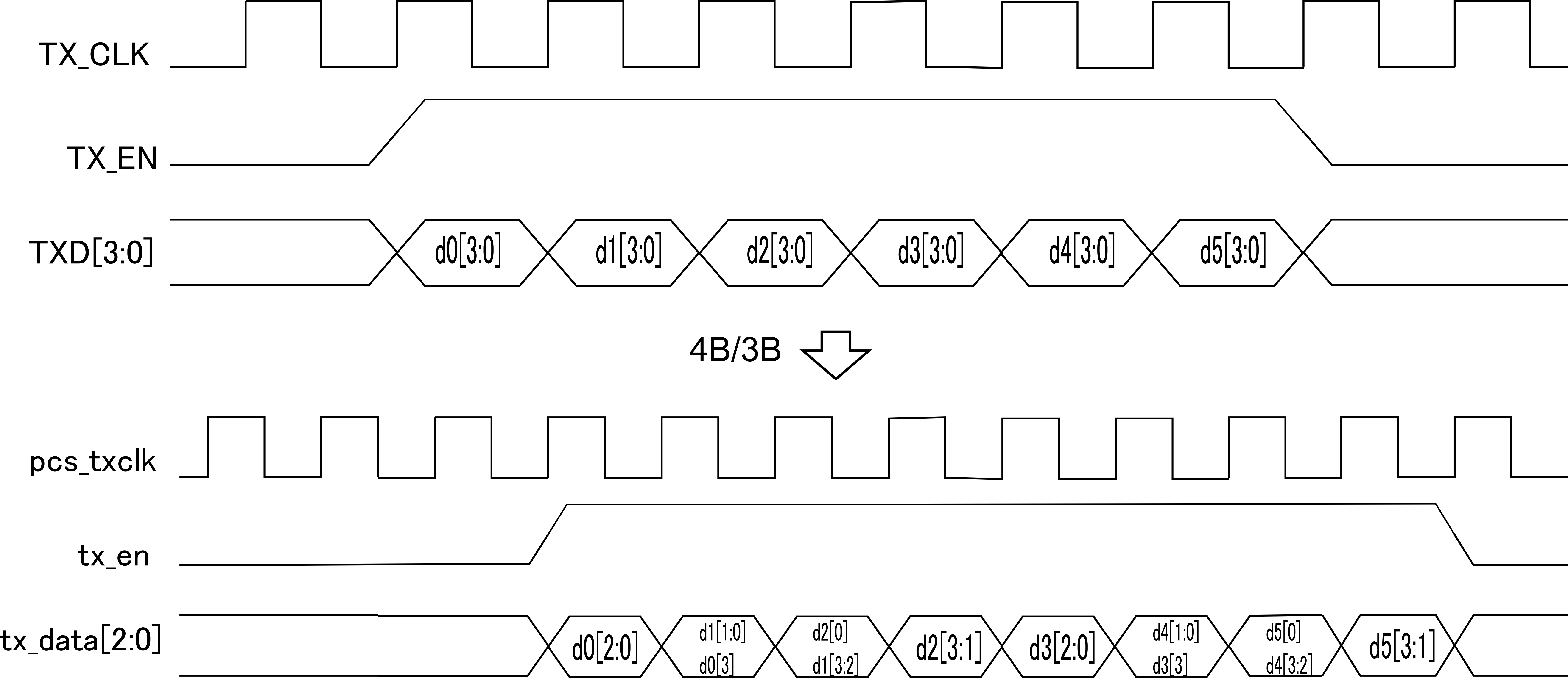
100BASE-T1 PHY processes the data received from MAC as follows.
・4B/3B
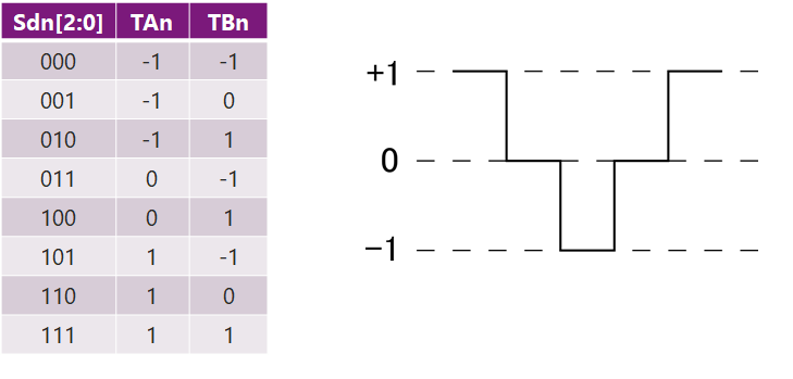
・3B2T
·scramble
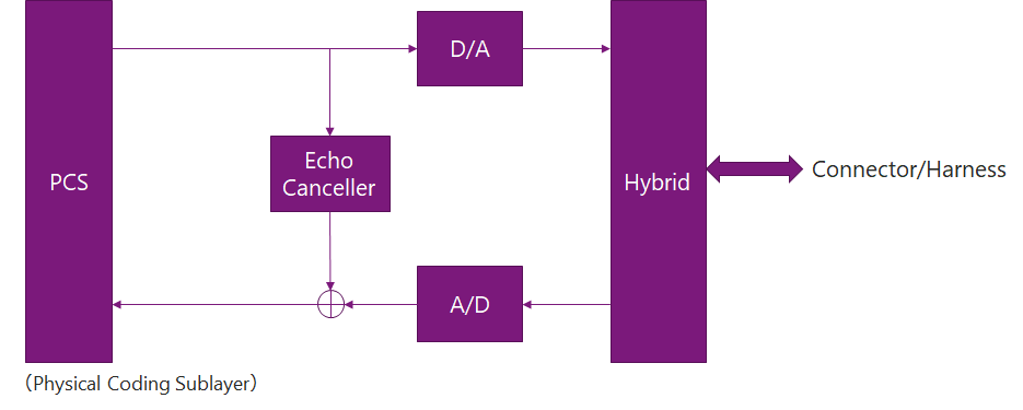
The 100BASE-T1 PHY uses 4B/3B encoding. In 4B/3B, it is sampled with a 33.333MHz clock inside the PHY (see Figure 1). After that, it is scrambled according to the generator polynomial and finally converted to a ternary signal called PAM3. Conversion to PAM3 signals follows the 3B2T mapper (see Figure 2). By using this PAM3 signal, 100Mbps communication is realized at a symbol rate of 66.666MBd. In addition, the PHY contains a hybrid circuit and an echo canceller, which separates the received and transmitted waveforms by comparing them with the original transmitted waveforms, enabling paired transmission and reception (see Fig. 3).
About 1000BASE-T1 PHY
1000BASE-T1 PHY processes the data received from MAC as follows.
・80B/81B
・3B2T
·scramble
・RS-FEC encoding
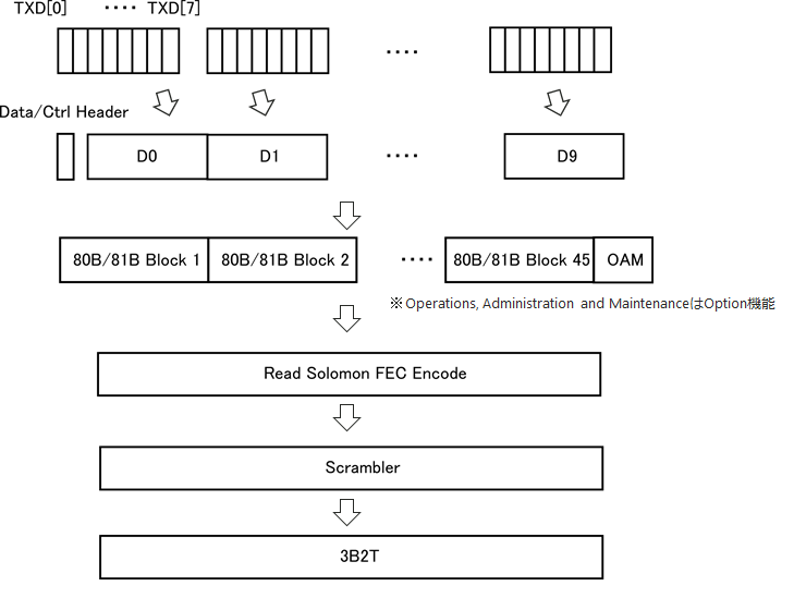
80B/81B receives 8-bit data from MAC and takes 10 clock cycles to make 80-bit. The remaining 1 bit is added with a header that distinguishes whether it is a data block or a control block. 45 80B/81B blocks are collected and a field called OAM is added.
RS-FEC encoding is then performed, RS-FEC parity bits are added for error correction, and scrambled. Such processing is required for the 1000BASE-T1 PHY to meet the IEEE specified bit error rate of less than 10^-10. Ultimately, like 100BASE-T1, it is converted to a PAM3 signal and transmitted.
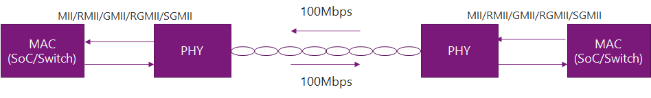
What is MII
MII (Media Independent Interface) is used for the interface between PHY and MAC. When selecting a PHY, it is necessary to check the supported interfaces. The main interfaces are shown in the table.
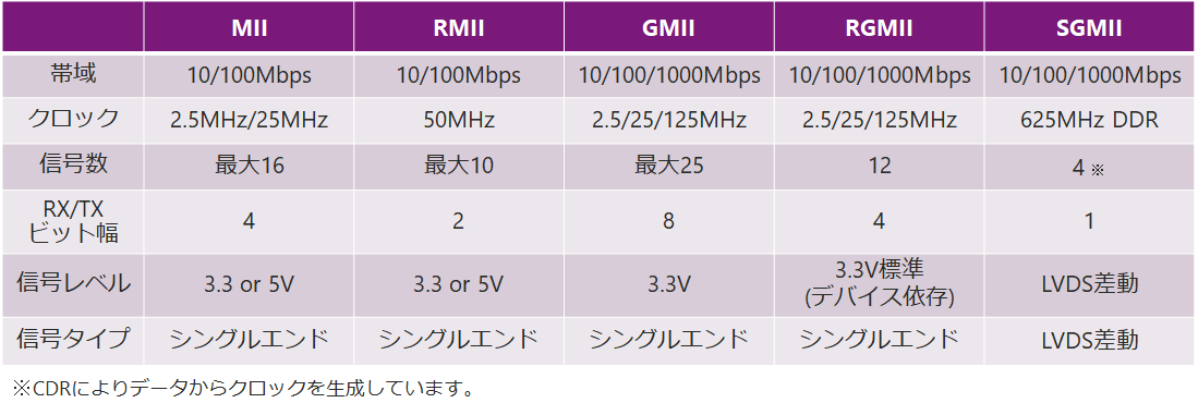
MII: Media Independent Interface
RMII: Reduced Media Independent Interface
GMII: Gigabit Media Independent Interface
RGMII: Reduced Gigabit Media Independent Interface
SGMII: Serial Gigabit Media Independent Interface
* RvMII (Reversed Media Independent Interface)
An interface used to connect MACs like SoC devices and Switch devices. If you select RvMII on the Switch device when only MII is supported by the SoC device, the clock can be supplied from the Switch device to the SoC device, making it possible to connect/communicate even under such circumstances.
Click here for the article on Episode 2 In-Vehicle Ethernet Switch
Part 2 explains the basic operation of the Ethernet Switch.