- Semiconductor BusinessHOME
- Products and Services of Macnica,Inc.
-
technical information

-
Events and Seminars
- Handling Manufacturer
- Support
- Inquiry
- Click here to purchase products
- Semiconductor business e-mail magazine registration
![]()
![]() Narrow down by specifying conditions
Narrow down by specifying conditions
現在2189件がヒットしています。check

Connect a pull-up or pull-down resistor if you want to give an IC empty pin or logic. At that time, the resistance value is probably selected "somewhat" and "appropriately". Or you may be using resistance simply because you've been doing it for a long time without thinking too much about why it's necessary.
This time, let's think about this resistance value.
Purpose of pull-ups and pull-downs
There are three main purposes of pull-ups and pull-downs.
(1) To avoid opening empty terminals (or unused terminals)
(2) to intentionally give a high or low logic
(3) To provide logic when all bus outputs are disabled
Consider each one.
To avoid opening empty terminals (or unused terminals)
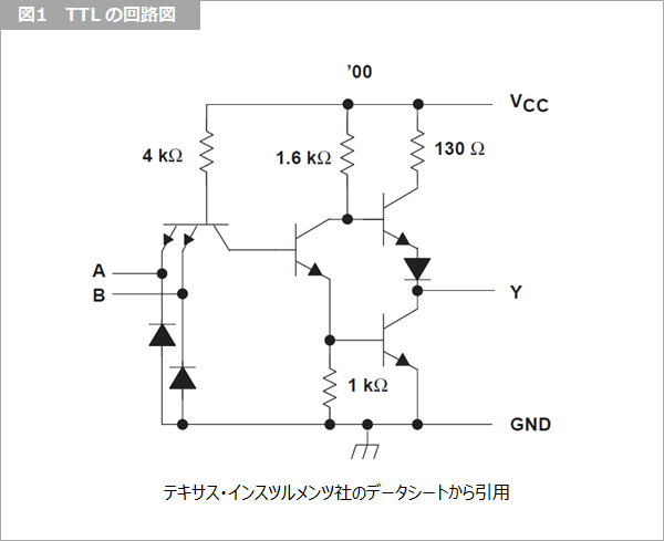
Figure 1 is the TTL 7400 schematic. When the input is open, the input transistor acts as an inverse transistor, allowing current to flow from base to collector. Since this state is stable as it is, "(1) To avoid opening empty terminals (or unused terminals)" is unnecessary for TTL. Since unused terminals may be used later, it is better to leave them open.
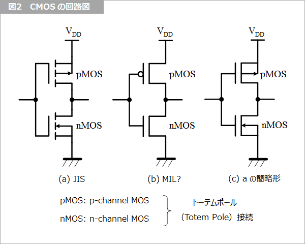
Figure 2 is a CMOS circuit diagram. As shown in the figure, CMOS has a vertically symmetrical circuit, so if the input is left open, the input will be at an intermediate level. , avoid leaving the input open. Therefore, connect it to power or ground to clamp the input high or low.
At this point, there is a "habit" of connecting high value resistors, especially not directly to the power supply. I guess that the reason for connecting this high resistance is that it is confused with the TTL case of "(2) intentionally giving logic of high or low".
To give intentional high or low logic
In the case of "(2) intentionally giving high or low logic", connect the TTL input to the power supply with a high resistance instead of connecting it directly to the power supply. The reason a resistor is needed is due to the TTL maximum rating.
The maximum rating for TTL is 7V supply voltage Vcc and 5.5V input voltage (footnote 1). The reason why the maximum rating of the input voltage is low is that, as shown in Figure 1, TTL has an emitter input, and bipolar transistors have a low reverse withstand voltage between the emitter and base. Therefore, if the input is connected to the power supply voltage, the input may be destroyed if the power supply voltage is increased to 5.5V or higher during power supply margin tests. For this reason, it was recommended to connect a resistor.
The resistor value must be determined from the TTL's input current. The 7400 standard for input current is IIH<40uA@2.4V. Therefore, in order to secure 2.4V when Vcc=4.75V (minimum value), it is necessary to make Rpullup<(4.75V-2.4V)/40uA=59kΩ. I believe that this custom took hold when it was transferred to CMOS, and the rule of "when pulling up, connect to the power supply via a resistor of several tens of kΩ" became established.
CMOS may be connected directly to the power supply if it gives a high. Either TTL or CMOS can be tied directly to ground to provide a low. However, when verifying prototype circuits, you may want to apply opposite logic or signals to terminals set high or low. For that purpose, it is good to pass through a high resistance without connecting directly to the power supply or ground. The upper limit of the resistor value should be set so that it is determined high or low for the maximum input current, as in the TTL example above.
The lower limit of the resistance value is determined assuming that an output with another logic is connected. Assuming that the weakest (smallest) driver is 4mA and Vcc is 3.6V (max), VOL is 0.4V and (3.6V-0.4V)/4mA=800Ω. I don't think such a small resistor is usually used, so I don't need to think about the lower limit. Of course, if there is no possibility to add contrary logic, we will connect directly.
In both cases of "(1) avoiding opening of empty terminals (or unused terminals)" and "(2) intentionally providing high or low logic", pull-up or pull-down resistors are applied to input terminals in advance. may be built in. In that case, of course, no external resistance is connected.
To provide logic when all bus outputs are disabled
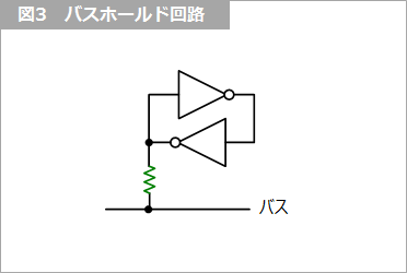
When assigning logic to the bus in “(3) To provide logic when all bus outputs are open (disabled)”, the upper limit of the resistance should consider the total leakage current of the I/O pins. to decide. If 8 devices with a leakage current of 20uA are connected to the bus, it will be 160uA. Assuming a power supply of 3.0V (min), in order to secure a high of 2.4V, (3.0V-2.4V)/160uA=3.75kΩ, which is a smaller value than expected. As mentioned above, I don't think the lower bound needs much consideration. When applying logic to the bus, using a bus hold circuit with a latch as shown in Figure 3 will hold the logic before the bus is released.
Footnote 1
As an exception, LS TTL is a diode input, so the maximum input voltage rating is the same as the power supply voltage, 7V.
What is Yuzo Usui's Specialist Column?
It is a series of columns that start from the basics, include themes that you can't hear anymore, themes for beginners, and also a slightly advanced level, all will be described in as easy-to-understand terms as possible.
Maybe there are other themes that interest you!