- Semiconductor BusinessHOME
- Products and Services of Macnica,Inc.
-
technical information

-
Events and Seminars
- Handling Manufacturer
- Support
- Inquiry
- Click here to purchase products
- Semiconductor business e-mail magazine registration
![]()
![]() Narrow down by specifying conditions
Narrow down by specifying conditions
現在2165件がヒットしています。check

To make a flash circuit made with an LED driver, you need to estimate the output capacitor. In this article, I will explain in detail how to make a constant power (CP) circuit, which is important when estimating the capacitors required for a flash circuit using LTspice.
If you are just starting LTspice, we recommend that you look at the "basics" from the list below.
Let's use LTspice series list is here
Also, if you would like to see a video on how to write a basic circuit and how to execute it, there is an on-demand seminar that does not require you to enter personal information, so please take a look if you are interested. Detailed information about the seminar is also provided to those who fill in the questionnaire.
LTspice On-Demand Seminar - Function check with RC circuit -
How to make a variable resistor
To make a constant power circuit with LTspice, refer to the article "Let's make a variable resistor" below.
As written in this article, the resistance value can be treated as a parameter.
In other words, it means that the resistance value can be controlled by the input voltage and the output voltage, and constant power power supplies and loads can be created.
A method of charging a capacitor with constant power while limiting the input current and voltage
Here, we present a technique for charging a capacitor with constant power while limiting the input current and voltage.
The circuit diagram is as follows, and assumes specifications such as an input voltage of 6V, a limit current of 1A, an efficiency of 80%, and a charging voltage of 20V.
Since it is assumed that the input voltage is 6V and the output is 20V, some people may think that a booster circuit is necessary, but it is a simple circuit that does not use a DC/DC converter. Since charging (originally controlled by a DC/DC converter) is important, there is no problem even if the input voltage is set higher than the output voltage. Rather, the current flows from high voltage to low voltage, so it is better to set it to a sufficiently high voltage.
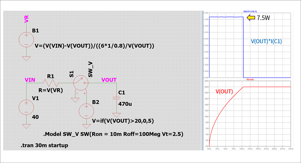
The assumed input is 6W with a voltage of 6V and a current of 1A. And if the efficiency is 80% when passing through the DC/DC converter, the power required as input is 6W/80%=7.5W. We want to control the power to be constant by the value of R1 for current limit, so set as follows.
Capacitor voltage = VOUT
W = V*I
W = VOUT * I ・・・①
W = 6V * 1A / 80%…②
From ① and ②,
I = (6V * 1A / 80%) / VOUT
Since we use R as a variable resistor VR,
(VIN - VOUT) / VR = I
Than
VR = (VIN - VOUT) / ((6V * 1A / 80%) / VOUT)
From the formula above
VR = (VIN - VOUT) / ((6V * 1A / 80%) / VOUT)
is required, so the behavior power supply outputs a voltage called VR.
Since the output at VR is a voltage, enter "R=V(VR)" in the parameter of resistor R1 and use the value calculated by the behavior power supply as the resistor value. As a result, as you can see from the graph in Figure 1, you can see that the power input to the capacitor is always 7.5W.
How to estimate capacitor value in constant power circuit
Next, we will explain how to connect a constant power load and estimate the required capacitor value.
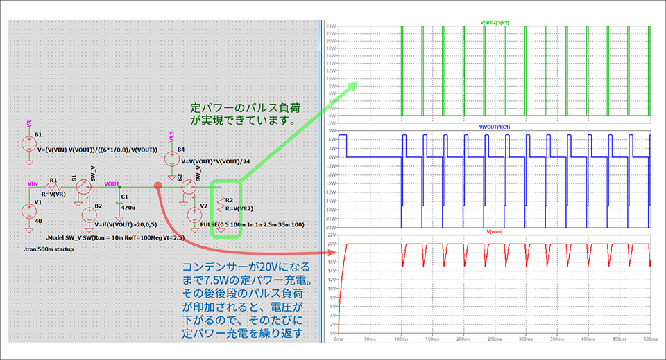
Figure 2 is a circuit diagram with a constant power load added to the previous circuit (Figure 1).
With it, you can quickly calculate, for example, how much capacitance you need in your energy bank, how much output capacitor you need in your LED driver, etc., without using the actual DC/DC.
This circuit provides a constant power charge to an energy bank of capacitors (470uF) and stops charging when fully charged (20V).
After that, a constant power load (here, 24W) is turned on (connected) with an On Duty of 2.5ms at a frequency of 30Hz to discharge the capacitor. A switch is used to turn the load ON/OFF.
How to make a constant power load
I will explain how to make a constant power load added in Fig. 2.
W=VI
V=IR
From the basic principles above
R=V/I
I=W/V
Than
R=V^2/W
becomes.
Therefore, the voltage of the capacitor becomes the input voltage of the load, so in order to set the load to a constant power of 24W, enter the following equation into the behavioral power supply as in the previous circuit.
V=V(VOUT)*V(VOUT)/24
This completes the constant power load circuit.
By constructing such a circuit, when considering a flash circuit using an LED driver, it is possible to easily perform simulations in advance to determine what kind of power should be stored in what kind of capacitor.
The simulation model used this time
Click here for recommended seminars/workshops
Analog Devices Manufacturer Information Top
If you want to return to Analog Devices Manufacturer Information Top, please click the button below.