- Semiconductor BusinessHOME
- Products and Services of Macnica,Inc.
-
technical information

-
Events and Seminars
- Handling Manufacturer
- Support
- Inquiry
- Click here to purchase products
- Semiconductor business e-mail magazine registration
![]()
![]() Narrow down by specifying conditions
Narrow down by specifying conditions
現在2168件がヒットしています。check

Loop characteristics of automotive primary DC/DC converters
Loop characteristics, that is, the phase margin and gain margin of the internal error amplifier, are one of the important factors in obtaining stable operation within the specifications of the DC/DC converter. In this article, I will explain the points to note regarding the phase margin adjustment of the Primary side DC/DC that uses a 12V automotive lead-acid battery (hereinafter referred to as +B) as the power source.
I will omit the concepts, calculation formulas, adjustment methods, etc. for obtaining the phase margin and gain margin, but since these depend on the peripheral components used in the circuit and the usage specifications, if there are factors with large variations, adjustment is required. In particular, +B requires a wide voltage range, and it can be said that one of the difficulties is that direct connection DC/DC converters require careful adjustment due to entanglement with peripheral components.
In this article, we performed a simulation comparison using the following two power sources.
・Applications that use an AC adapter (12V output) as a power source
For example, in the case of an application that uses an AC adapter (12VDC output) as a power source, there are many cases in which designs are made with an input voltage variation of approximately ± 10% taken into account.
・Applications that use +B as the power source
Variation is even greater, and in many cases 9Vin to 16Vin is considered as an initial design. Furthermore, it is necessary to consider the cold-cranking factor, and it is assumed that stable operation will be required at a voltage value lower than 9Vin (such as 5V at IC end voltage).
Simulation with LTPowerCAD
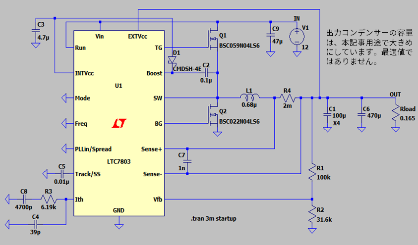
Let's simulate the phase margin and gain margin with LTpowerCAD.
Constant ⇒ LTC7803 : 12Vin/3.3Vout, Iout=20A, Fsw=500KHz, Ith: R3= 10KΩ, C8=560pF, C4=22pF
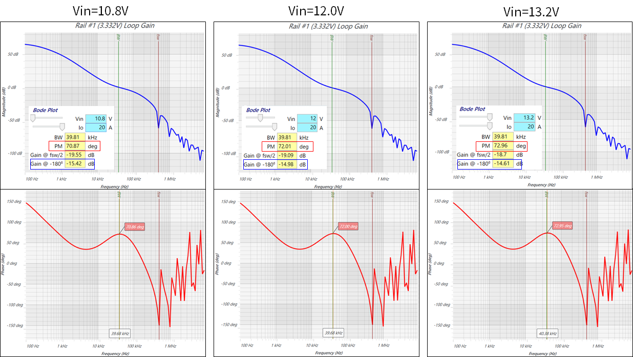
Result of application powered by AC adapter (12V output)
|
Vin |
10.8V |
12.0V |
13.2V |
|
Bandwidth |
39.81 [KHz] |
39.81 [KHz] |
39.81 [KHz] |
|
Phase Margin |
70.87 [deg] |
72.01 [deg] |
72.96 [deg] |
|
Gain |
(-)15.2 [dB] |
(-)14.98 [dB] |
(-)14.61 [dB] |
Table 1: Simulation results assuming an AC adapter (12Vin±10%)
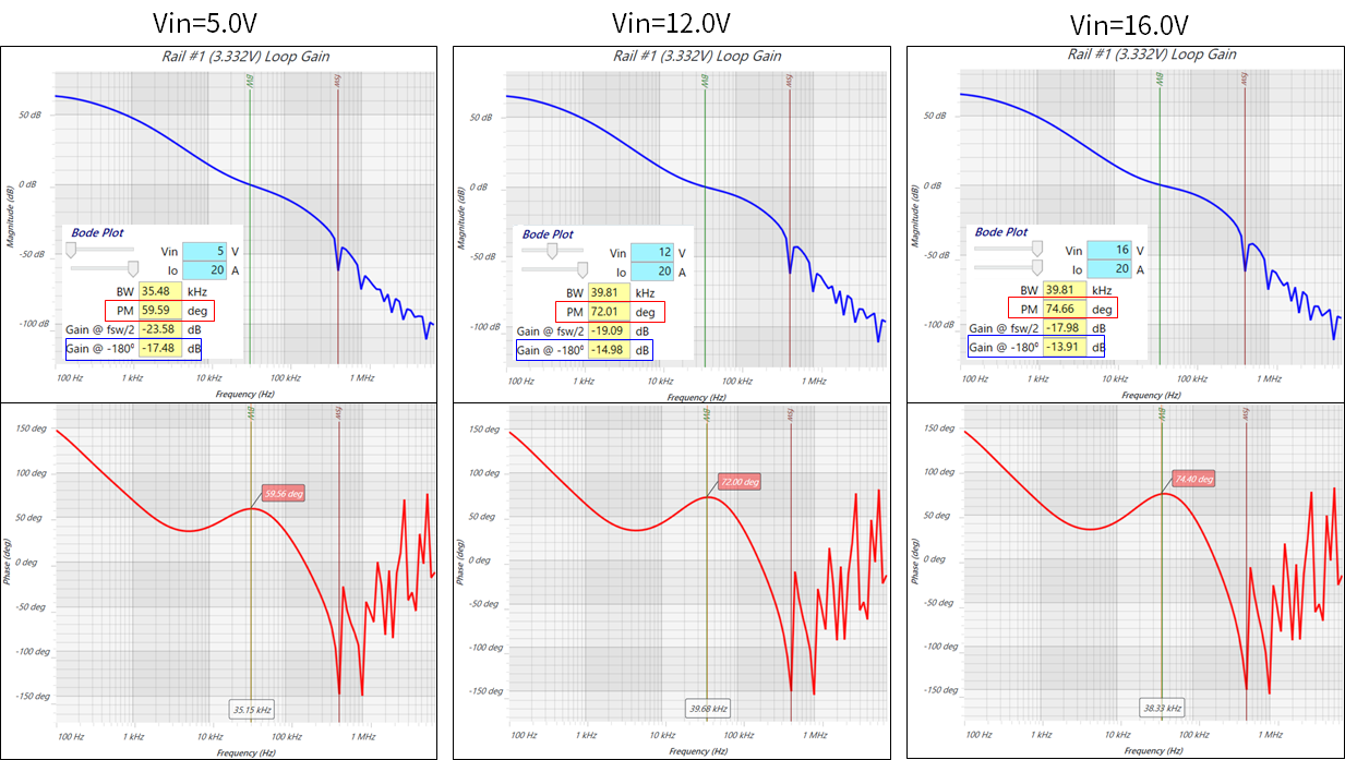
+B Powered Application Results
|
Vin |
5.0V |
12.0V |
16.0V |
|
Bandwidth |
35.48[KHz] |
39.81 [KHz] |
39.81 [KH] |
|
Phase Margin |
59.59 [deg] |
72.01 [deg] |
74.66 [deg] |
|
Gain |
(-)17.48 [dB] |
(-)14.98 [dB] |
(-)13.91 [dB] |
Table 2: +B assumption with Cold-Crank (5Vin to 16V) simulation results
Differences found from simulation results
As shown in the above simulation results, there is a clear difference in the characteristics when +B is assumed to be 5V, which is considered to be the effect of the wide input range. From a general point of view, this result is not a bad value, but in this simulation, the ambient temperature was set to Ta = 25 °C, so the temperature swing test was performed on the actual machine, and there was a further difference. In some cases, the possibility of needing adjustment is not zero.
In automotive applications, the basic temperature environment is Ta = -40 °C to 85 °C, and depending on the installation location, Ta = -40 °C to 125 °C is required, making it a harsh environment.
How to adjust loop characteristics
R3:
Crossover frequency "FC "Adjustment of: FC teeth Gain But 0dB frequency of time
Decreased resistance→ FC Small, increased resistance → FC Big
Phase margin and load responsiveness tend to be trade-offs.
FC Adjust according to the customer's application whether to lower the responsiveness instead of lowering the difficulty of securing the phase margin by reducing , or to use the opposite pattern.
C8: gain adjustment
Capacitance value decrease → Gain small, Capacitance value increase → Gain large
Although the settling time tends to increase with a large gain, the load response Over/Undershoot without changing the voltage FC can be made smaller.
with small gain Over/Undershoot The voltage will be smaller and the settling time will be reduced, but FC, the phase margin tends to decrease.
C4: Formation of high frequency pole (for noise reduction)
It can be expected to be effective mainly in removing noise in the high frequency band.
Cff: Phase lead adjustment (this time 0pF setting)
Advances the high frequency phase to improve the load response characteristics. Adjusted in consideration of the phase margin.
Also, although it is a little out of the topic of this article, I will list the selection of the inductor constant from the viewpoint of entanglement with peripheral components. The inductor ripple current is highly dependent on the input voltage range for a fixed output voltage and switching frequency.
+B But Min/Max The constant should be chosen keeping in mind that the amplitude of the ripple current will also be very large if it swings out to . And when the inductor constant is changed, the phase margin Gain so that the margin is optimal, R3, C8, C4 or Cff The constants also need readjustment.
In order to obtain stable operation based on these assumptions, it is necessary to adjust the optimum loop characteristics.
Click here for recommended seminars/workshops
Inquiry
In this article, we have introduced the importance and precautions of adjusting the loop characteristics of automotive DC/DC converters. For more information, please contact us below.
Analog Devices Manufacturer Information Top
If you want to return to Analog Devices Manufacturer Information Top, please click the button below.